
Tone Burst Generator Circuit

The circuit utilizes two integrated circuit gates, IC1-a and IC1-b, configured as a monostable multivibrator. The monostable multivibrator is characterized by a single stable state and a temporary unstable state triggered by an input signal. The timing characteristics of the circuit are determined by the resistor R3 and capacitor C2, which define the duration of the output pulse.
When the transmitter is dekeyed, the signal at TX+ transitions to a low state, which pulls pin 1 of IC1-a low momentarily. This low signal serves as a trigger for the monostable, initiating the timing sequence. As C2 begins to charge through R3, the voltage across C2 rises until it reaches the threshold voltage of IC1-b, at which point the monostable output transitions, causing pin 3 to go low.
The timing period, noted to be around 700 ms in the prototype, is critical for ensuring that the output pulse is of adequate duration to be effective while remaining inaudible. This characteristic is essential in communication applications where the timing of signals can influence the clarity and integrity of the transmitted information.
In scenarios where immediate rekeying occurs, the TX+ signal returns to a high state while the monostable is still active. This condition allows for the oscillations generated by IC1-c to be integrated into the transmission signal. The enabled state of the buffer gate IC1-d facilitates the passage of the oscillation signal to the output, ensuring that any tone generated during this period is effectively transmitted. This function is particularly useful in applications where tone signaling is required in conjunction with data transmission.
The overall design demonstrates a robust application of monostable multivibrator principles, effectively integrating timing control and signal transmission functionalities in a compact configuration. Integrated circuit gates ICl-a and TCl-b form a monostable, whose time constant is determined by C2 and R3. When the transmitter is dekeyed (and then almost immediately rekeyed) point TX+ goes low and takes pin 1 low for a short time.
This triggers the start of the timing period controlled by C2/R3. The capacitor C2, charges via R3 until the trigger point of gate ICl-b is reached. At this point, the monostable changes state and pin3 goes low again. On the prototype, this time was about 700 ms. The pulse occurs each time after dekeying and it is normally inaudible. If, however, point TX+ goes high again (as in immediate rekeying) the monostable is still in the enabled state and the oscillations of ICl-c are present in the transmission. During this time period, the buffer gate, ICl-d, is enabled and the tone is therefore passed to the output.
Related Circuits
This is a small circuit designed as an insect repellent, targeting mosquitoes and birds by producing high-frequency audio signals. These signals interfere with the hearing of insects, making it unbearable for them, causing them to flee. The operation of...

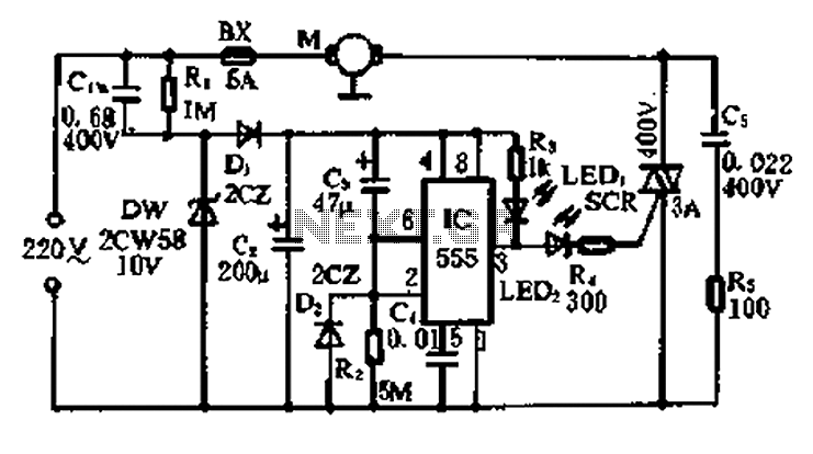
A simple and easy-to-implement one-way flashing lights string controller is designed for small shop or home decoration. This device utilizes a thyristor-based dimmer circuit, which operates effectively by managing large capacitance. The circuit includes a ten-microfarad capacitor connected to...
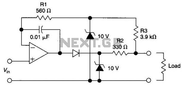
The circuit is designed to drive an external load. A fault condition in the external load circuit could feed excessive current or voltage back into the line drive circuit. If excessive voltage appears from the load, the two zener...
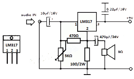
The LM317 integrated circuit (IC) is commonly recognized as a voltage regulator; however, it can also function as an audio amplifier. This low-power amplifier circuit designed with the LM317 provides a maximum output of approximately 1 watt. The LM317...
A 5-minute circuit can continue to operate during a power outage, providing protection for the refrigerator. The refrigerator power protection circuit, designated as 1136, includes a power transformer that converts 220V voltage through a rectifier bridge (VD1). This setup...
Very little extra circuitry is needed to do both forward and backward walking sequences along with a few other tricks. The PIC16F818 has a lot of features that work well in this situation. As you can see from the...