
Tone Control

The tone control circuit is designed to adjust the frequency response of an audio signal, allowing for enhancement or attenuation of specific frequency ranges. This circuit typically employs a combination of capacitors and resistors to create filters that modify the audio signal's bass, midrange, and treble characteristics.
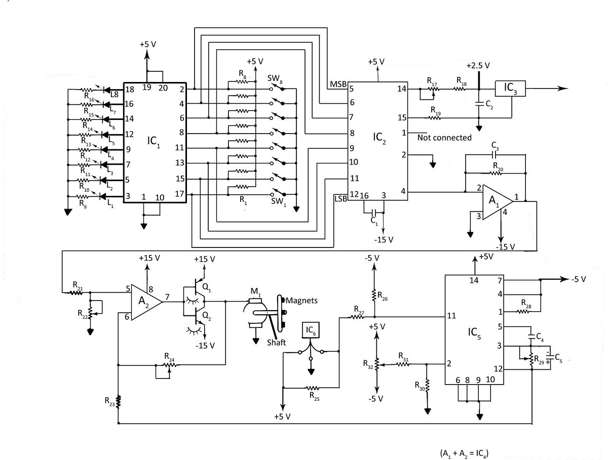
In this particular tone control circuit, there are two types of capacitors utilized: six 2.2µF electrolytic capacitors and two 0.05µF ceramic capacitors. The electrolytic capacitors (C1, C3, C5, C7, C15, C16) are primarily used for coupling and decoupling applications, where they help to block DC voltage while allowing AC signals to pass. Their larger capacitance value is suitable for low-frequency applications, making them ideal for bass enhancement in the tone control circuit.
The ceramic capacitors (C2, C6), with a smaller capacitance value of 0.05µF, are typically used for high-frequency filtering. These capacitors are known for their stability and reliability, making them suitable for treble adjustments. The combination of these capacitors allows the tone control circuit to effectively shape the audio signal across a wide frequency range.
The overall design of the tone control circuit may incorporate potentiometers or variable resistors, which enable users to adjust the level of bass, midrange, and treble. By manipulating these controls, the user can achieve the desired tonal balance for various audio sources, enhancing the listening experience.
In summary, the tone control circuit described is an essential component in audio systems, providing flexibility in sound customization through the strategic use of electrolytic and ceramic capacitors.Tone Control. Parts: Part Total Qty. Substitutions C1, C3, C5, C7, C15, C16 6 2.2uf Electrolytic Capacitor C2, C6 2 0.05uF Ceramic. 🔗 External reference
Related Circuits
The advanced credit card, referred to as the "microcontroller super card," incorporates numerous innovative enhancements. The initial step involved verifying the code and subsequently uploading it to the Arduino board. The developed code enabled a counter to increment from...
Various techniques can be employed to control the speed of a DC motor, including phase-locked-loop principles, digital inputs, or analog inputs. Additionally, the motor's speed can be monitored using LED or LCD displays. The digital DC motor speed controller...
This simple DC motor control or PWM circuit using a 555 IC can be utilized to regulate the speed of a DC motor. The circuit is straightforward and can be assembled quickly if all components are readily available. The described...
An initial post to share work on remotely controlling the PXA-70x Multimedia controllers. The target for the new installation is under consideration. The PXA-70x Multimedia controllers are sophisticated devices used in various audio-visual setups, often found in automotive and home...
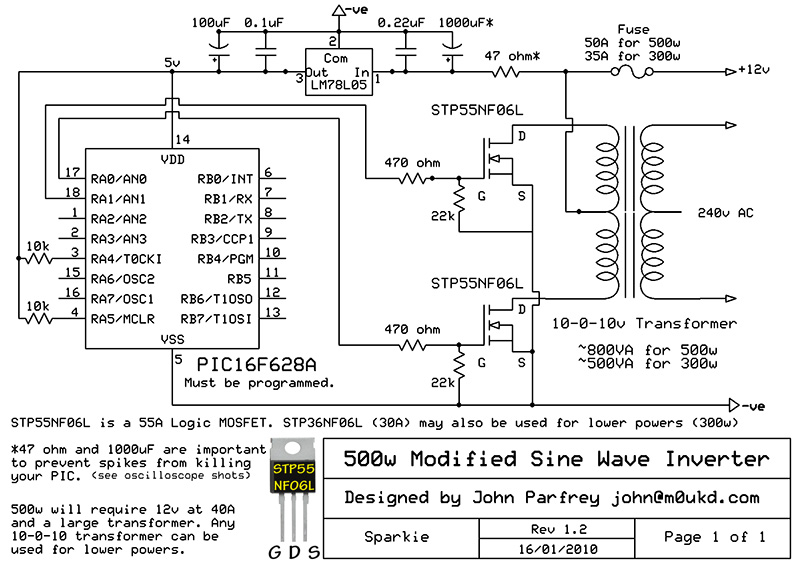
PIC controlled 500W Modified Sine Wave Inverter. The PIC16F628A is programmed to produce a logic 5V signal for 5ms at pin 17, followed by 15ms off. The described circuit implements a 500W modified sine wave inverter controlled by a PIC16F628A...
The project originated from a request by Tony Bowler, a member of the Long Eaton Club, who sought assistance in converting a "Golden Oldie" model to electric free-flight. He selected Vic Smeed's "Debutante" to be powered by seven AE...