
dc motor control pwm 555

The described circuit employs a 555 timer IC configured in astable mode to generate a pulse-width modulation (PWM) signal. The frequency and duty cycle of the PWM signal can be adjusted by varying the resistor and capacitor values connected to the 555 timer. This modulation allows for precise control over the average voltage supplied to the DC motor, effectively adjusting its speed.
Key components of the circuit include the 555 timer IC, a potentiometer for adjusting the resistance, and a capacitor to set the timing intervals. The motor is connected to the output of the 555 timer through a transistor, which acts as a switch to handle the higher current required by the motor. Additional components may include diodes for flyback protection, ensuring that voltage spikes generated by the motor when it is turned off do not damage the circuit.
The schematic layout typically features the 555 timer IC at the center, with connections to the potentiometer and capacitor forming the timing circuit. The output pin of the 555 timer connects to the base of the transistor, which is used to control the motor. A power source is connected to the motor and the transistor's collector, while the emitter is grounded.
This PWM circuit is not only efficient but also minimizes heat generation compared to linear control methods, making it suitable for various applications where speed control of DC motors is necessary. The simplicity of the circuit allows for easy integration into larger systems or for educational purposes in understanding motor control techniques.This simple DC motor control or PWM circuit using 555 IC can be used to control the speed of a DC motor. The circuit is very simple and can be built in very short time if all parts are available with you.. 🔗 External reference
Related Circuits
555 Timer with Audio Alarm Circuit. This circuit serves as a straightforward electronic timer equipped with an audio alarm feature. The 555 timer is a versatile integrated circuit widely used in various timer, delay, pulse generation, and oscillator applications. In...
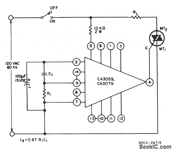
This circuit utilizes a CA3059 or CA3079 zero-voltage switch to manage the turn-on timing of a triac. The delay between the closure of the switch and the activation of the triac is determined by the resistor (R) and capacitor...
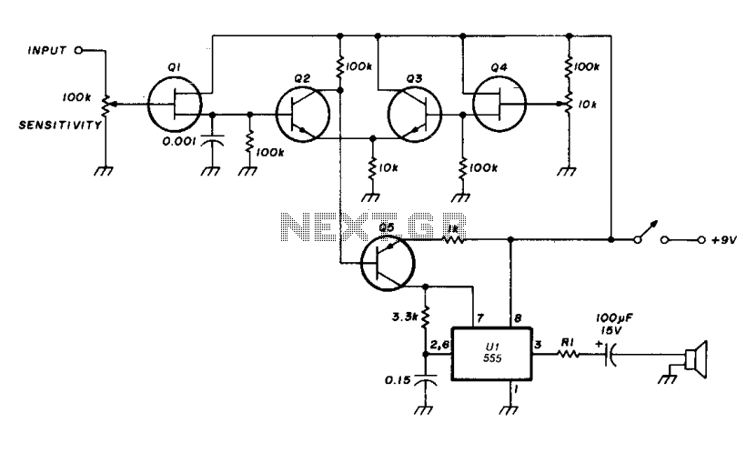
The transistor Q5 and the 1000-ohm resistor form the variable element necessary for controlling the frequency of the voltage-controlled oscillator (VCO) by limiting the charging current flowing into the 0.15 microfarad timing capacitor based on the forward bias applied...
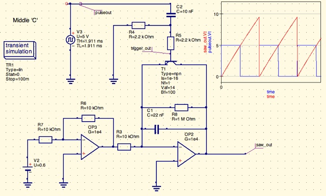
A design for a digitally controlled analog oscillator is being developed. The control voltage is generated by a microcontroller (Arduino) and is utilized through two operational amplifiers, along with a resistor and capacitor network that forms an integrator circuit....
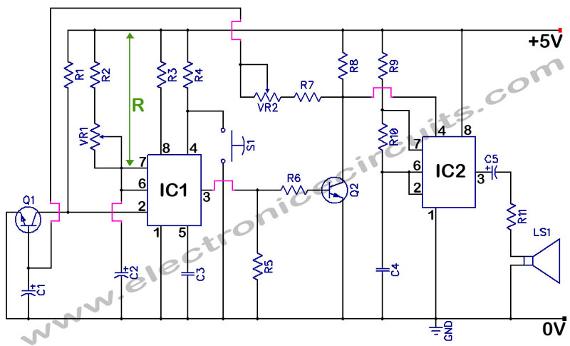
This beeper circuit utilizes two 555 integrated circuits (ICs) and can operate within a supply voltage range of 5 to 15V DC. It is suitable for applications requiring an alarm or beeping signal. The first IC (IC1) is configured...
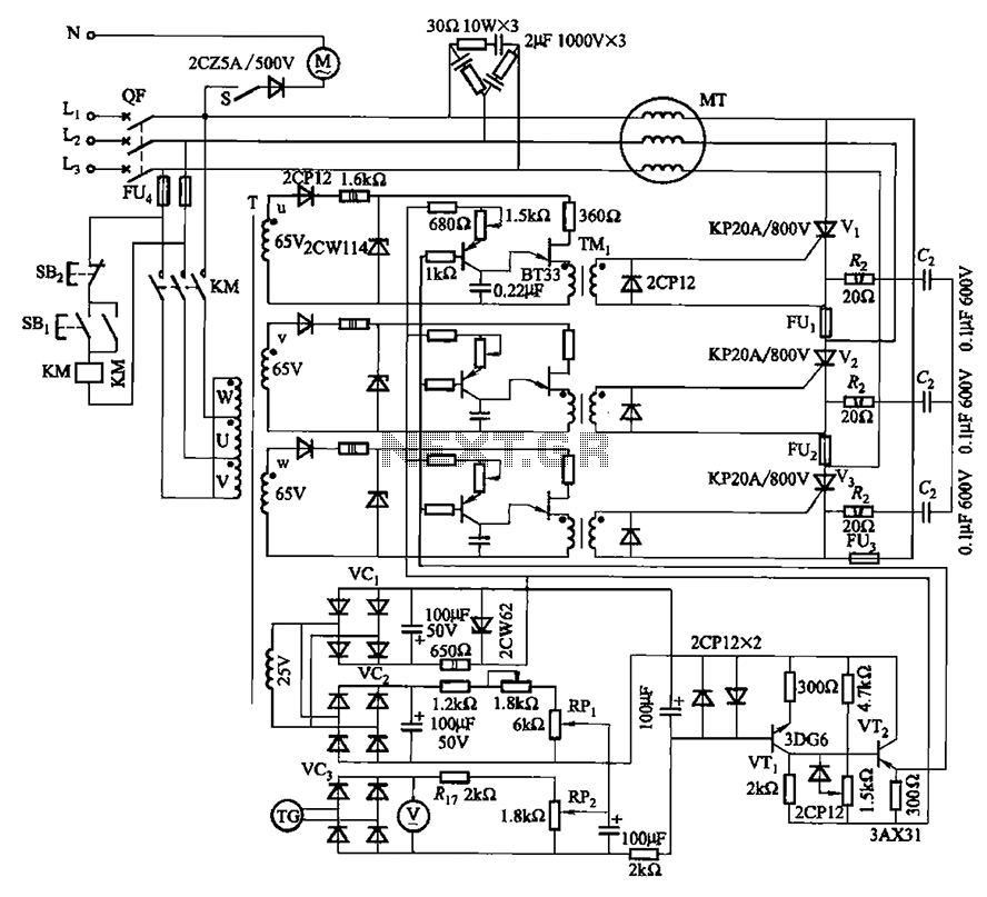
The circuit depicted in Figure 3-181 comprises three thyristors, labeled V1 to V3. The trigger circuit utilizes a single-junction transistor relaxation oscillator. The speed control circuit incorporates negative feedback. A master adjust potentiometer, designated as RPi, is used to...