
Tone Control Schematic

The Baxendall tone control circuit is a widely utilized configuration in audio applications for adjusting the tonal quality of sound signals. It typically consists of a series of resistors and capacitors arranged to provide frequency-dependent gain adjustments. In this specific implementation, the circuit allows for a maximum cut and boost of approximately 10dB at both 10kHz and 50Hz, which are common frequencies of interest in audio processing.
The first transistor, designated as Q1, is configured in a common-collector (also known as an emitter follower) arrangement. This configuration is essential as it provides high input impedance while offering low output impedance, effectively isolating the tone control section from the subsequent stages of the circuit. This buffering capability is crucial in preventing loading effects that could alter the frequency response of the tone control.
The second transistor, Q2, is employed to provide a slight gain boost to the output signal. However, it is important to note that the overall gain of the Baxendall circuit is inherently less than unity due to its passive nature; the tone controls themselves do not amplify the signal but rather adjust the frequency response. The design is optimized to interface with amplifiers that have input impedances ranging from 10kΩ to 250kΩ, ensuring compatibility with a wide range of audio equipment.
The passive nature of the Baxendall circuit means that it relies on the reactive components (capacitors and inductors) to shape the audio signal rather than active amplification. This results in a smooth tonal adjustment without introducing significant distortion, making it a preferred choice in high-fidelity audio applications. The careful selection of component values will dictate the precise frequency response, allowing for tailored adjustments to suit specific audio characteristics.Based on the classic Baxendall tone control circuit, this provides a maximum cut and boost of around 10dB at 10KHz and 50Hz. As the controls are passive, the first transistor, Q1, is configured as common-collector to act as a buffer stage.
The last transistor, Q2, provides a slight boost. Note that the gain of the output of the Baxendall circuit is less than one because of passive nature of it. The output is designed to feed an amplifier with input impedance of 10kohms to 250kohms. 🔗 External reference
Related Circuits
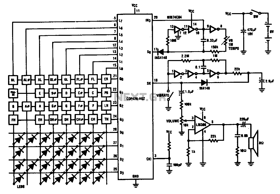
Twenty-five musical keys and 25 LEDs are provided to denote F to F" with half notes in between. Memory can store a played tune. There are ten preprogrammed tunes (each has an average of 55 notes) masked in the...
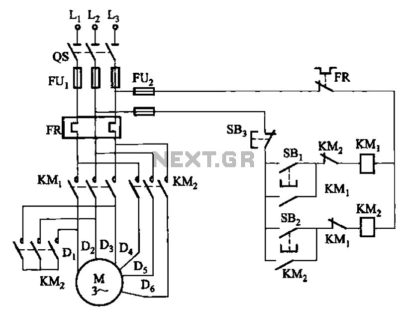
The circuit illustrated in Figure 3-97 features two contacts and is designed specifically for a 2kW dual-speed motor. In this configuration, SB1 is utilized for low-speed operation, while SB2 serves as the high-speed run button. The circuit operates by allowing...
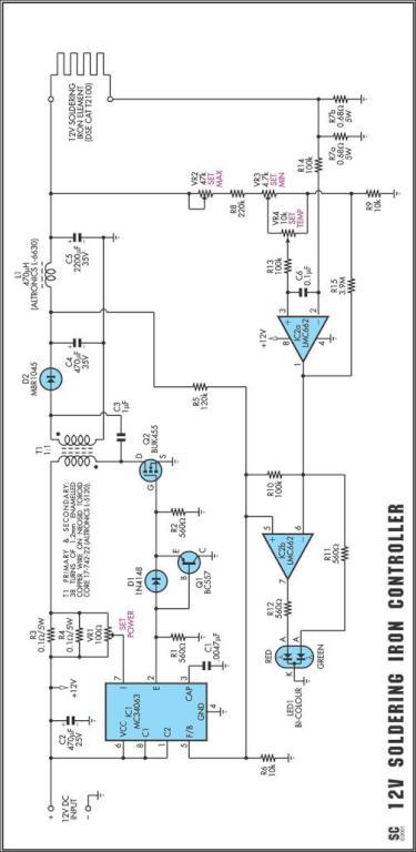
One reason why commercial soldering stations are expensive is that they typically require soldering irons with built-in temperature sensors. Commercial soldering stations are designed to provide precise temperature control and consistency during soldering operations, which is essential for achieving reliable...
The Up Alarm is designed to provide an audible alert when sunlight is detected or when a light source is activated in a dark environment. It can also be utilized to sense various light sources such as beams or...
Children enjoy the siren sounds of police or fire brigade vehicles. This circuit is capable of generating a dual tone similar to the siren sounds of police or fire brigade cars. This circuit typically... This circuit is designed to replicate...
This AC drill speed controller circuit schematic allows for the control of the drilling speed of a borer or drilling machine. This project is based on the principle that... The AC drill speed controller circuit is designed to modulate the...