
Tone generator with 555

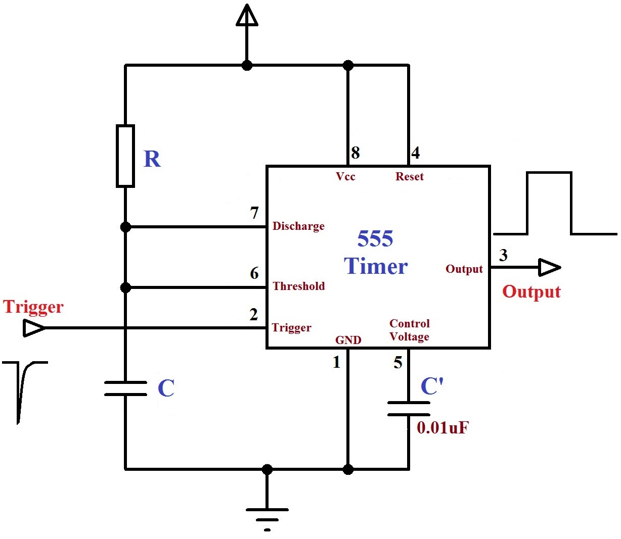
The described circuit utilizes the 555 timer IC in an astable configuration, which allows it to operate as a continuous oscillator. In this setup, the 555 timer generates a square wave output that can be used to create audio tones. The frequency of oscillation is determined by the values of two resistors and a capacitor connected to the timer.
In this specific design, one of the resistors is a potentiometer, which serves as a variable resistor, allowing for adjustable frequency control. By altering the resistance, the pitch of the generated tone can be modified, providing a simple means of sound modulation. The capacitor connected to the circuit plays a critical role in stabilizing the output by filtering out noise, ensuring that the adjustments made with the potentiometer result in smooth transitions in pitch rather than abrupt changes.
For practical applications, the circuit can be implemented with minimal components, making it cost-effective and easy to assemble. It is particularly suitable for projects requiring audio signals, such as alarms or sound effects. Additionally, the circuit can be adapted for Morse code applications by incorporating a switch at the output. This modification allows the user to manually control the tone generation, enabling the transmission of Morse code signals effectively.
Overall, this 555 timer-based oscillator circuit exemplifies a straightforward yet versatile design that can be employed in various electronic projects requiring sound generation.This circuit is based around the 555 timer circuit, used as an astable (free running) oscillator. The frequency (pitch) of the tone is set by the resistors and capacitors in the left side of the circuit. The first one is a potentiometer (variable resistor), this is our pitch control, which is basically all the external components you need.
The capacitor to the far left is to reduce as much noise or undesired operation of the potentiometer, getting a smooth pitch change when adjusting. Simple, low component count tone generator. It can be adapted to create a morse code circuit, by adding a switch to the output. 🔗 External reference
Related Circuits
This project is a basic code practice oscillator designed for beginners to learn Continuous Wave Morse Code. It utilizes a 555 timer to produce a "dit" or "dah" sound when the key is pressed. The circuit employs a 555 timer...

The astable multivibrator is an oscillator circuit that generates continuous pulses without requiring any external triggering. The oscillation frequency and time period can be manually adjusted by modifying the values of resistors R1, R2, and capacitor C1. A 555...

The circuit is designed to enable rapid changes in motor speed and direction by utilizing four outputs to drive a MOSFET H-bridge. The lower rail power MOSFETs are N-channel devices, while the upper rail MOSFETs are P-channel. All MOSFETs...
The monostable mode of the 555 Timer operates by having one stable state and switching to an unstable state for a predetermined time period T when triggered. The time period T is determined by the RC time constant in...

The circuit generates a warble-tone alarm signal that simulates the sound of a British police siren. IC1 is configured as an alarm generator, while IC2 operates as a 1 Hz astable multivibrator. The output from IC2 is utilized to...
This simple circuit has helped me out on many occasions. It is able to check transistors, in the circuit, down to 40 ohms across the collector-base or base-emitter junctions. It can also check the output power transistors on amplifier...