
Transistor Checker with 555

The circuit described is a transistor tester that utilizes a 555 timer integrated circuit (IC) and a dual flip-flop IC (4027) to provide a simple yet effective means to test NPN and PNP transistors. The 555 timer is configured in astable mode to generate a square wave output at approximately 12 Hz. This output is fed into the 4027 flip-flop, which serves to divide the frequency by two, resulting in complementary outputs that alternate between high and low states.
The outputs from the flip-flop are connected to two light-emitting diodes (LEDs), designated as LED1 and LED2, through a current-limiting resistor (R3). The arrangement of the LEDs is such that they are oriented in opposite polarities. When the circuit is powered without a transistor connected, both LEDs will blink alternately, indicating the circuit is functioning properly.
When a transistor is connected to the tester, the base of the transistor is linked to a junction formed by two additional resistors (R4 and R5). If a good NPN transistor is connected, it will allow current to flow, causing LED1 to illuminate consistently. Conversely, if a good PNP transistor is tested, LED2 will light up. In situations where the transistor is open (non-functional), both LEDs will flash, indicating a lack of conduction. If the transistor is shorted, both LEDs will remain off, signaling a fault condition.
This circuit provides a visual and straightforward method for testing transistors, making it an invaluable tool for electronics troubleshooting and repair. The use of common components such as the 555 timer and 4027 flip-flop ensures that the circuit is both cost-effective and easy to assemble.This simple circuit has helped me out on many occasions. It is able to check transistors, in the circuit, down to 40 ohms across the collector-base or base-emitter junctions. It can also check the output power transistors on amplifier circuits. Circuit operation is as follows. The 555 timer ( IC1 ) is set up as a 12hz multi vibrator. The output on pin 3 drives the 4027 flip-flop ( IC2). This flip-flop divides the input frequency by two and delivers complementary voltage outputs to pin 15 and 14.
The outputs are connected to LED1 and LED2 through the current limiting resistor R3. The LED's are arranged so that when the polarity across the circuit is one way only one LED will light and when the polarity reverses the other LED will light, therefore when no transistor is connected to the tester the LED's will alternately flash. The IC2 outputs are also connected to resistors R4 and R5 with the junction of these two resistors connected to the base of the transistor being tested. With a good transistor connected to the tester, the transistor will turn on and produce a short across the LED pair.
If a good NPN transistor is connected then LED1 will flash by itself and if a good PNP transistor is connected then LED2 will flash by itself. If the transistor is open both LED's will flash and if the transistor is shorted then neither LED will flash.
🔗 External reference
Related Circuits
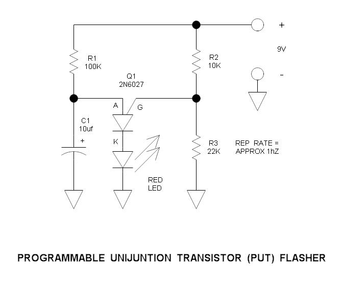
This is a simple circuit that illustrates the function of the programmable unijunction transistor. It can be quickly wired on a proto-board. The circuit utilizes a programmable unijunction transistor (PUT) to demonstrate its operation as an oscillator. The PUT, which...
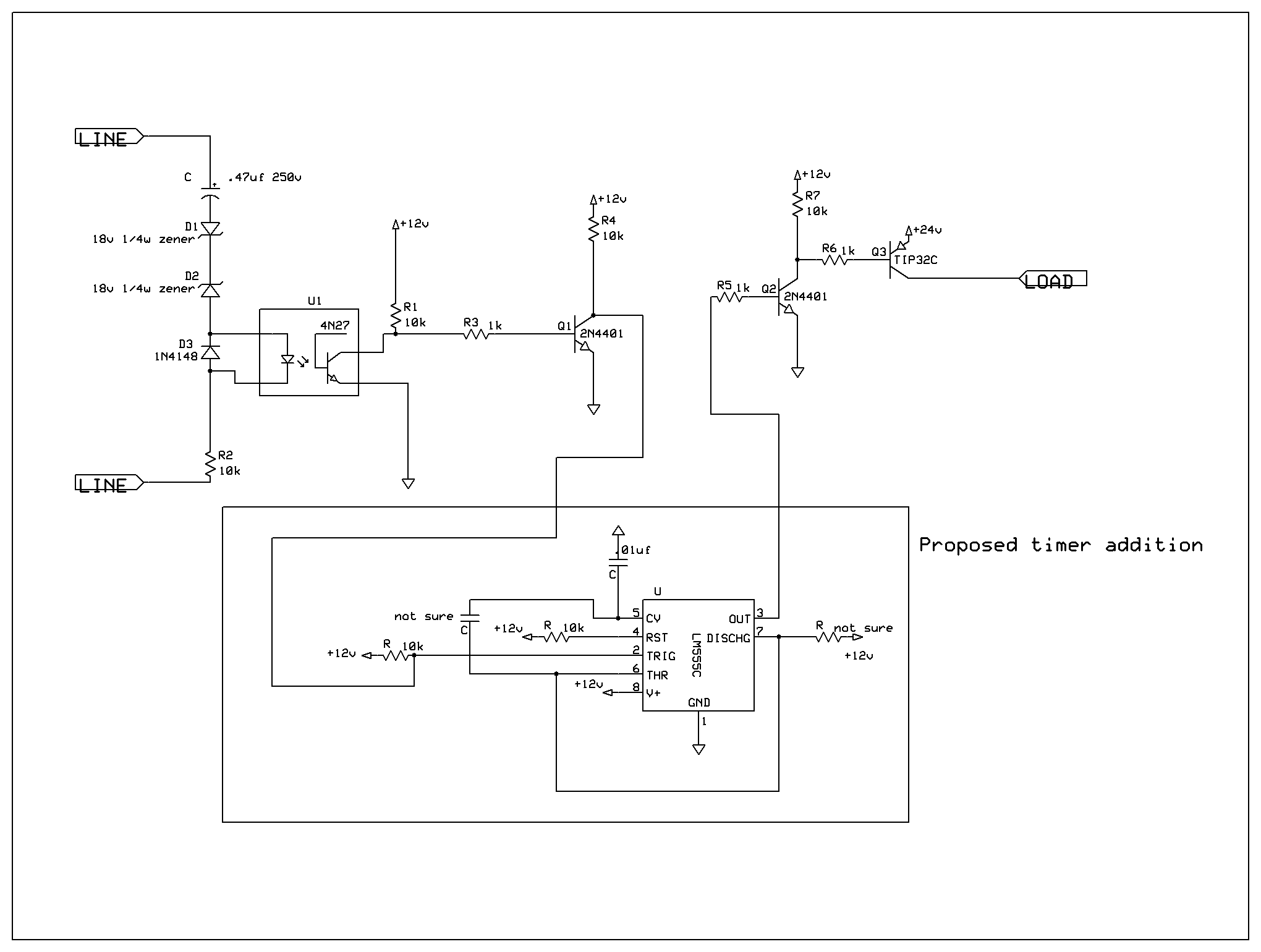
A ringer interface circuit is designed to buffer the output of a central telephone system, which connects to multiple ringers distributed throughout a building. This circuit addresses an issue where the line overloads when ringing, requiring a reset. The...
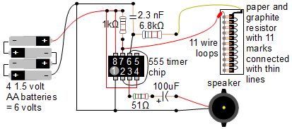
A simple music instrument/keyboard is created using a 555 timer chip circuit, a piece of paper, and a pencil. The project includes a more advanced automatic music player that utilizes a playing head and a long sheet of paper...
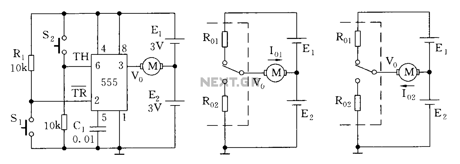
The 555 timer in bistable mode has fewer applications compared to its stable and monostable modes. Bistable mode refers to the circuit configuration based on the R-S (Reset-Set) trigger mode. An example of this is a micro-motor reversing control...
The control terminal at 5 feet and the threshold end at 6 feet represent two internal input voltage comparators. As long as the voltage at 6 feet exceeds the voltage at 5 feet by 5 mV, the 555 timer...
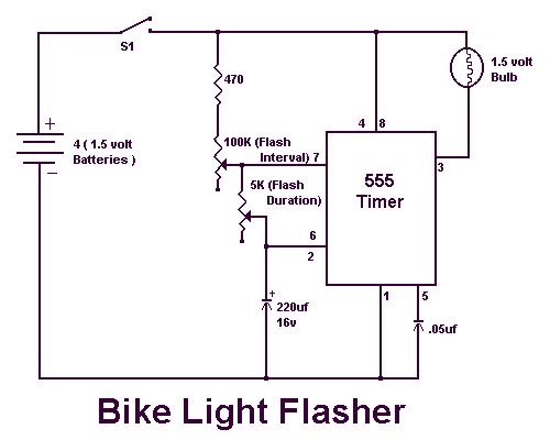
I ride my bike allot at night and sometimes I'm not sure if people can see me. This circuit will flash an incandescent light that you can purchase from Radio Shack. Adjust the VR's for your flash requirements and...