
Code Practice Oscillator Using 555 Timer

The circuit employs a 555 timer configured in astable mode, which allows it to generate a square wave output. This output frequency can be adjusted to create the distinct sounds associated with Morse Code. The circuit consists of a few key components: the 555 timer IC, resistors, capacitors, and a push-button switch.
When the push-button switch is pressed, it activates the 555 timer, causing it to oscillate at the predetermined frequency. The frequency of the output signal can be controlled by varying the resistor and capacitor values in the timing circuit. A typical configuration might use a resistor in the range of 1kΩ to 10kΩ and a capacitor of around 10µF to 100µF. This combination will generate the desired frequencies for "dit" (short beep) and "dah" (long beep) sounds.
To ensure the output is audible, the 555 timer is connected to a small speaker or piezo buzzer. The audio output can be further amplified if necessary, depending on the application and the desired volume level. A simple low-pass filter may also be added to smooth out the output waveform, reducing harmonics and providing a cleaner sound.
The circuit can be powered by a standard 9V battery or a DC power supply, making it portable and easy to use in various environments. This project not only serves as a practical introduction to the 555 timer and basic electronics but also provides a fun way to learn Morse Code through auditory signals.This simple code practice oscillator project for beginners to Continuous Wave Morse Code uses a 555 timer to generate a dit or dah sound when the key is pressed 🔗 External reference
Related Circuits
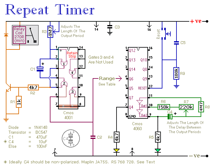
This circuit features an adjustable output timer that can re-trigger at regular intervals. The output duration can range from a fraction of a second to half an hour or more, and it can be configured to recur at intervals...

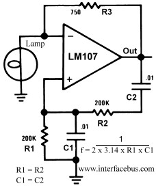
A Wien bridge oscillator generates sine waves with a very low distortion level. It produces zero phase shift at only one frequency (f = 1/2πRC), which becomes the oscillation frequency. Stable oscillation can only occur if the loop gain...
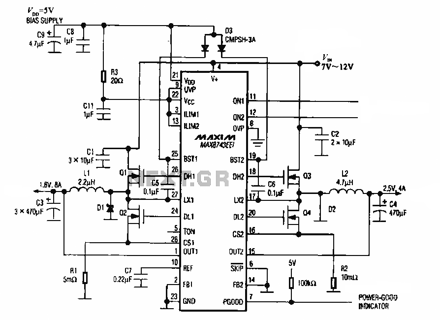
The circuit utilizes the MAX8743 chip for a laptop chipset power supply. It demonstrates the conversion of a 5V power supply into +2.5V and +1.8V outputs. The MAX8743 is a highly integrated power management solution designed specifically for laptop chipsets....
This is a lamp timer capable of operating two separate relay switches. Outputs can be in three (or restricted to two) states: OFF, delayed ON and constant ON. Delayed ON mode is indicated by the LEDs. The source code...
This circuit generates a 10Hz sine wave using a minimal number of components, based on the specified component values. The active components are generic and can be substituted as needed. The passive component values determine the frequency and should...
This voltage-to-frequency converter (VFC) circuit utilizes a 555 integrated circuit (IC) and a 741 operational amplifier (op-amp) as its primary components. The circuit is capable of generating oscillations of up to 20 kHz. The voltage-to-frequency converter circuit is designed to...