
Tone selector circuit

The schematic represents a sophisticated tone control system designed for audio applications, allowing users to tailor the sound output to their preferences. The five-speed tone selector provides versatility in sound adjustment, enabling fine-tuning of audio characteristics. The use of a T-type network in conjunction with various feedback loops and passive components ensures that the amplifier maintains a desired frequency response while allowing for enhancements in specific audio ranges.
The circuit's design incorporates a combination of resistors and capacitors to create a stable and adjustable equalization effect. The negative feedback loops are crucial in maintaining linearity and preventing distortion, which is vital for high-fidelity audio reproduction. The inclusion of a bandpass filter further refines the audio output, ensuring that only the desired frequency ranges are amplified, thus enhancing the overall listening experience.
In operation, the user can easily switch between different tone settings using the interlocking key switch, which mechanically prevents multiple selections from being activated simultaneously. This feature ensures reliable operation and prevents potential signal interference that could arise from simultaneous engagement of different tone control settings. Overall, the design reflects a careful consideration of audio engineering principles, emphasizing clarity, control, and user flexibility in sound modulation.Figure 4-12 is a five-speed type tone selector schematics o as follows: circuit, IC1 and other components electromagnetic phono equalizer amplifier, I bar and external RC compo nents and composition of the selection switch tone tune selector circuit. Press the straight button, sAl, SA2 action, SAi negative feedback loop in the T-type network c8.. Rs disconnect, saz will C7 short-circuit to be a typical linear amplifier gain is determined by the advocate 3 (R5 + R6), having a flat output characteristic straight. Press the Language key, SAi ~ SPk action, SAl, SA2 position with the straight key, the amplifier frequency response was flat state.
SA3, SA4 at the amplifier input termination people bandpass filter passband is. :, 200 ~ 3000Hz band signal by a 6dB/f audio attenuation. When you press the play button, carved altar of the parallel operation of a resistor R4 on the C7, the high-bass slightly improved. When you press the orchestral key, SA7 action, T-type network people are short-circuited, C8 ground bass are to be mentioned liters.
Press the bass is key, S: Ag, SAio action, catch the negative feedback loop capacitor b, C series, treble negative feedback enhanced bass can be improved, SAio with the network of T-type people and the resistance R7, so treble slightly, the discharge pitch bass balance electricity use 5 4 interlocking key switch.
Related Circuits
This microphone preamplifier utilizes the low-noise integrated circuit (IC) uA739. The circuit serves as an example of an effective design for preamplifying dynamic microphones. The IC contains two operational amplifiers. The uA739 is a precision integrated circuit known for its...
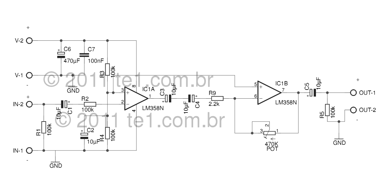
The LM358 series consists of two independent, high-gain, internally frequency-compensated operational amplifiers designed specifically to operate from a single power supply over a wide range of voltages. Operation from split power supplies is also possible, and the low power...
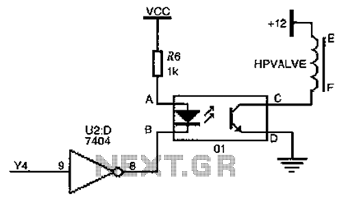
The driver circuit for the high-pressure natural gas shut-off valve utilizes solid-state relays. In dual-fuel mode operation, the fuel switching mechanism is controlled by a logic section that activates Y4 to a high state via U2 (7404 inverters). This...
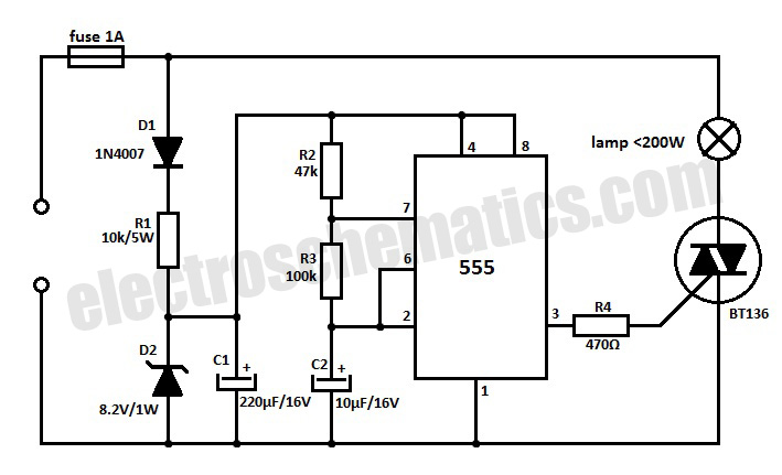
This 220V mains operated solid-state flashing lamp circuit utilizes a 555 timer integrated circuit (IC) to manage the ON and OFF durations of a triac that regulates power to the load. The circuit operates at a mains voltage of 220V,...
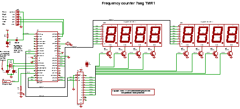
C code for a frequency counter circuit operating up to approximately 50 MHz, utilizing a multiplexed seven-segment display and employing Timer 1 to count the edges of the input signal. The frequency counter circuit described operates effectively within the range...
Approximately one watt RMS appears to be a suitable output level, which is also the maximum power that a basic amplifier powered by 12V can deliver to an 8 Ohm speaker. A very low saturation amplifier may reach up...