220V Flashing Lamp Circuit with 555
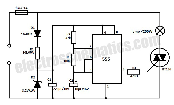
This 220V mains operated solid-state flashing lamp circuit utilizes a 555 timer integrated circuit (IC) to manage the ON and OFF durations of a triac that regulates power to the load.
The circuit operates at a mains voltage of 220V, making it suitable for standard electrical systems in many regions. The core component, the 555 timer IC, is configured in astable mode, allowing it to generate a continuous square wave output. This output toggles the state of the triac, which acts as a switch to control the power supplied to the lamp.
In this configuration, the 555 timer's frequency and duty cycle can be adjusted by varying the resistors and capacitors connected to its pins. This flexibility enables customization of the flashing rate and duration of the lamp illumination. The triac, when triggered by the output from the 555 timer, allows current to flow through the lamp, producing the flashing effect.
Additional components such as resistors and capacitors are used to filter and stabilize the circuit, ensuring reliable operation. A snubber circuit may also be implemented across the triac to protect it from voltage spikes, which can occur during the switching process. Proper heat sinking may be required for the triac to prevent overheating during prolonged operation.
This circuit design is ideal for applications requiring visual indicators, decorative lighting, or signaling devices, leveraging the efficiency and reliability of solid-state components. Proper safety measures should be taken during construction and operation, especially when dealing with high voltages.This 220V mains operated solid state flashing lamp circuit uses a 555 timer IC to control the ON and OFF times of a triac which controls power to the load 🔗 External reference


