
Touch Sensitive Light Dimmer

The SLB0586A is designed for touch-sensitive applications, providing a user-friendly interface for controlling lighting systems. This integrated circuit operates by detecting a touch input and modulating the output to adjust the brightness of connected lamps. The incorporation of the TIC206D, a triac suitable for controlling AC loads, allows for effective dimming functionality.
In the circuit, the SLB0586A receives a signal from a touch sensor, which can be implemented using a simple capacitive touch pad. Upon detecting a touch, the SLB0586A processes the input and sends a control signal to the TIC206D. The TIC206D, functioning as a switch, regulates the power delivered to the lamp by altering the phase angle of the AC voltage, thus controlling the intensity of the light emitted.
The circuit design typically includes additional components such as resistors and capacitors to filter signals and stabilize the operation of the IC. A snubber circuit may also be implemented across the TIC206D to protect against voltage spikes that could occur when switching inductive loads.
Overall, this touch light dimmer circuit presents a practical solution for modern lighting control, allowing for seamless adjustment of brightness through simple touch interactions while maintaining safety and efficiency in operation.With IC SLB0586A from Siemens you can build a simple touch light dimmer circuit that will allow you to adjust the lamp intensity. Together with a TIC206D.. 🔗 External reference
Related Circuits
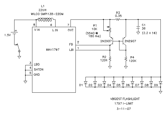
The goal was to create a compact flashlight that could be held in the mouth, easily stored in a pocket, and positioned on a surface to project light upwards. The budget was set at approximately $15, which was significantly...
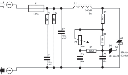
A potentiometer regulates the firing point of the triac. Capacitor C4 is charged through resistors R3, R4, P1, and R5. After a specific duration, determined by the potentiometer setting, the charge in C4 becomes sufficient for the diac D...
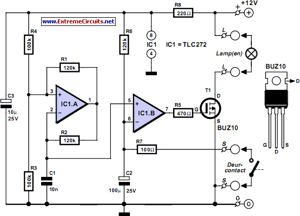
This circuit is relatively simple yet valuable, as it offers a high-quality interior light delay feature. The circuit for the interior light delay is designed to control the duration for which the interior lights remain illuminated after a door is...
Nowadays, a switch-off delay for vehicle interior lighting is a standard feature. However, certain models with minimal settings or older vehicles leave users in the dark as soon as they enter and close the door. This situation calls for...
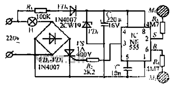
220V AC by Ri buck, Diao. C1 chain ferry flood ear, shouted for the regulator to 12V make C collapse. The film hand touch under ridicule the MT electrode films, clutter body. More: induction signal sent by See Cutting...
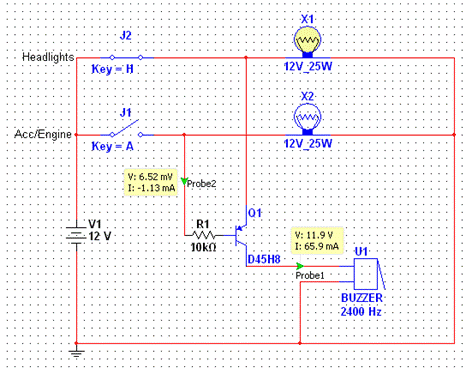
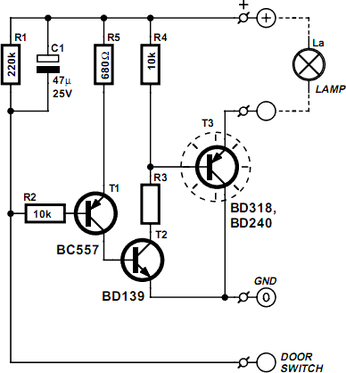
The most extreme option would be to supply power through a battery pack. A more plausible source would be the car's battery. However, since the objective of the circuit is to activate the buzzer when the headlights are on,...