
Luxury Car Interior Light Dimmer

The circuit for the interior light delay is designed to control the duration for which the interior lights remain illuminated after a door is closed or the ignition is turned off. It typically utilizes a combination of resistors, capacitors, and a transistor or relay to achieve the desired delay effect.
The core of the circuit involves a timing element, which can be implemented using an RC (resistor-capacitor) network. When the triggering event occurs—such as the closing of a door—the capacitor begins to charge through the resistor. The time it takes for the capacitor to reach a certain voltage level determines how long the lights will stay on. Once the threshold voltage is reached, the transistor or relay is activated, turning off the lights.
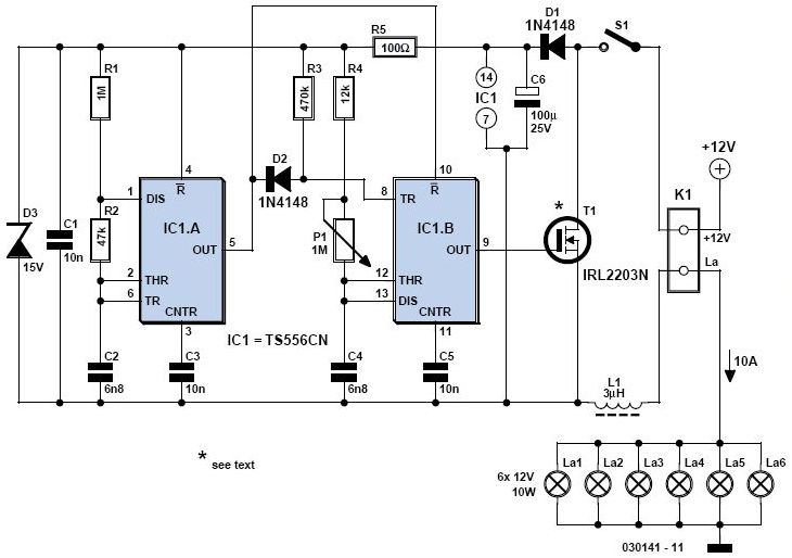
In more advanced designs, an integrated circuit (IC) may be employed to provide more precise timing control and additional features, such as adjustable delay settings or the ability to control multiple light sources. The circuit can be powered by the vehicle's battery, and it is essential to include protection components, such as diodes, to prevent back EMF from damaging the circuit when using inductive loads like relays.
Overall, this interior light delay circuit enhances the convenience and functionality of a vehicle's lighting system, ensuring that lights remain on for an appropriate period after the user has exited the vehicle.This circuit is much more modest, but certainly still worth the effort. It provides a high quality interior light delay. This is a feature that is include.. 🔗 External reference
Related Circuits
A light dimmer is quite uncommon in a caravan or on a boat. This document outlines how to create one, allowing for mood adjustment when needed. A light dimmer circuit is an essential component for enhancing the ambiance in confined...
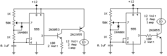
The schematic diagram illustrates a 12 Volt Car Lamp Dimmer Circuit Design utilizing a 555 Timer. This circuit can be employed to dim a standard 25-watt lamp. The 12 Volt Car Lamp Dimmer Circuit utilizes a 555 Timer in astable...
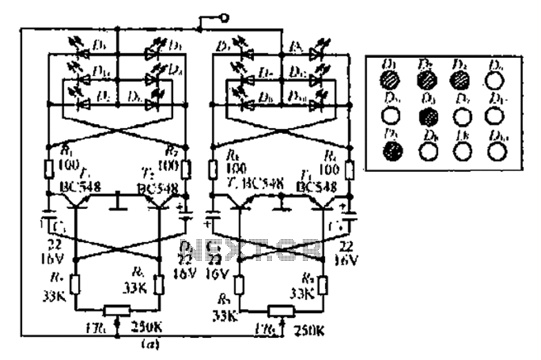
A circuit involving oscillations is composed of a Houle Wang oscillator that utilizes a transistor configuration with components labeled Ti, n, and n, along with a composition of Q constants for the cycle. The waveform can be modified by...
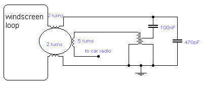
If you do not like the whip antenna on your car, you may try this alternative circuit. A one-turn loop is installed in the windscreen of the car, keeping possibly away from the metal structure of the car. This...
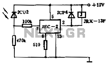
The circuit operates as a photoelectric switch utilizing a photoresistor. It exhibits high sensitivity, particularly in controlling a light relay. Under low illumination, the transistor (VT) remains non-conductive. When the illumination reaches a certain threshold, the resistance of the...
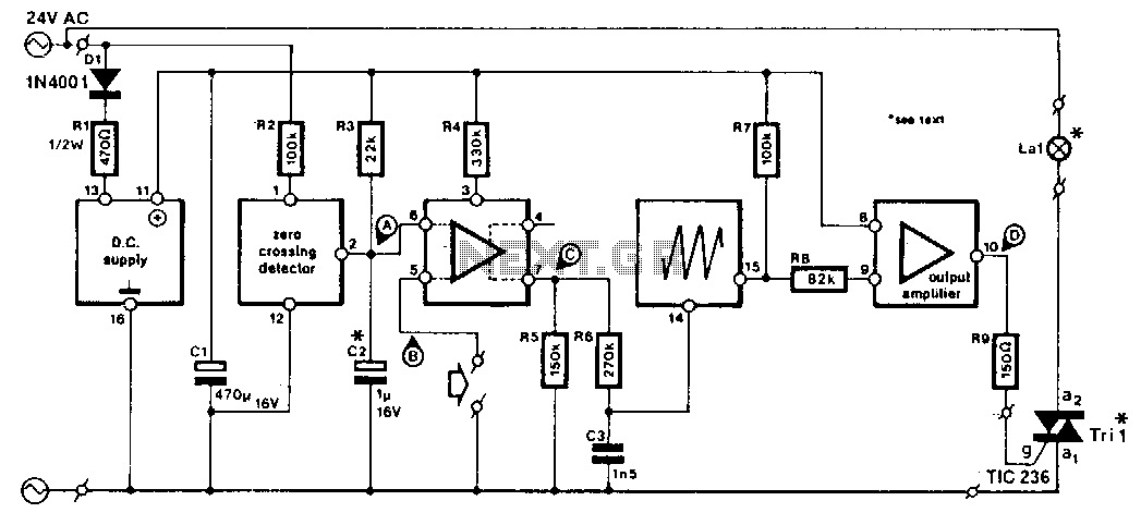
This circuit is designed for integration into slide projectors that lack a dimmer functionality, specifically for use with 24-V AC fed halogen lamps. With minor modifications, it can also be adapted for dimming 12-V halogen lamps, although it is...