
Touch-sensitive switch

The circuit employs a field effect transistor (FET), specifically Q1, to achieve a high impedance input. This characteristic is crucial for minimizing the loading effect on the preceding circuit stage, allowing for accurate signal processing. The FET operates by controlling the flow of current through its channel in response to an applied gate voltage, thus enabling the circuit to respond to low-level signals effectively.
The 741 operational amplifier serves as a voltage comparator, providing a threshold detection mechanism. When the input voltage exceeds a predetermined level, the op-amp output transitions, which then drives the base of Q2. As a medium current PNP bipolar transistor, Q2 is capable of handling the necessary current to energize the relay coil.
The relay acts as a switch, allowing for the control of higher power loads, such as motors, lights, or alarm systems, without directly interfacing with the sensitive components of the circuit. This configuration enhances the overall robustness of the system, ensuring that the low-power control signals can safely operate higher power devices.
In summary, this circuit design effectively combines a high impedance input stage with a voltage level detection mechanism and a power switching element, making it suitable for a variety of applications in automation and control systems.A high impedance input is provided by Ql, a general purpose field effect transistor 741 op amp is used as a sensitive voltage level switch which in turn operates the current Q2, a medium current PNP bipolar transistor, thereby energizing the relay which can be used to control equipment, alarms, etc.
Related Circuits
With a DPDT switch, I can switch the two data lines. I tried connecting the shields from the two computers together, the grounds two computers together, switching the D+ and D- lines with the DPDT switch, and leaving the...
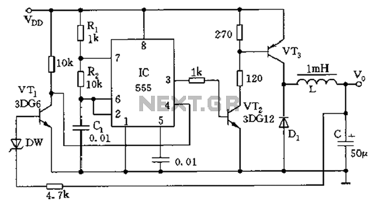
The circuit consists of a 555 timer configured as an astable multivibrator along with resistors R1 and R2 and capacitor C1. It generates an oscillation frequency of approximately 10 kHz with a duty cycle close to 50%. Transistors VT2...
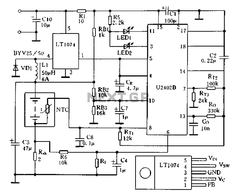
Charging circuit from the DC power supply switching power supply control The charging circuit described is designed to operate with a DC power supply, utilizing a switching power supply control mechanism. This type of circuit is commonly employed in applications...

This is a small circuit designed for use as a charging controller or voltage limiter. It is particularly useful for creating a solar charger. The assembly of the circuit allows for modifications according to personal preferences. The circuit is...
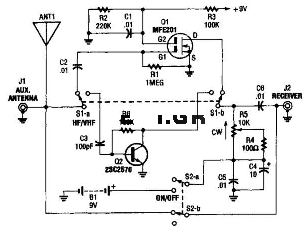
The AA-7 active antenna consists of two active components: Q1 (an MFE201 N-channel dual-gate FET) and Q2 (a 2SC2570 VHF silicon transistor), which form the foundation for two independent, switchable RF preamplifiers. The AA-7 active antenna is designed to enhance...
This temperature switch utilizes several discrete components to activate a buzzer when the ambient temperature rises. It is suitable for use as a straightforward fire alarm indicator. The temperature switch circuit is designed to monitor environmental temperature changes and provide...