Temperature Switch Project
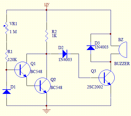
This temperature switch utilizes several discrete components to activate a buzzer when the ambient temperature rises. It is suitable for use as a straightforward fire alarm indicator.
The temperature switch circuit is designed to monitor environmental temperature changes and provide an audible alert when a specified threshold is exceeded. The core components typically include a thermistor or a temperature sensor, a comparator, and a buzzer.
The thermistor, which is a type of resistor whose resistance varies significantly with temperature, serves as the primary sensing element. When the ambient temperature increases, the resistance of the thermistor decreases, resulting in a voltage change across it. This voltage change is fed into a comparator circuit, which is configured to compare the voltage from the thermistor against a reference voltage set by a voltage divider.
When the temperature exceeds the predetermined limit, the output of the comparator switches state, signaling the activation of the buzzer. The buzzer is connected in such a way that it is energized when the comparator output goes high, producing an audible sound to alert individuals to the potential fire hazard.
Additional components may include resistors and capacitors for signal conditioning and delay, ensuring that the buzzer does not trigger from transient temperature fluctuations. A power supply, typically a battery or DC source, powers the entire circuit.
This simple yet effective design makes it suitable for various applications, including residential fire alarm systems, industrial safety monitoring, and other scenarios where temperature monitoring is critical. The circuit's simplicity allows for easy implementation and cost-effective production, making it an excellent choice for basic fire detection needs.This temperature switch uses a few discrete components to trigger a buzzer when the temperature of the surrounding increases. Suitable for use as a simple fire alarm indicator 🔗 External reference
