
Touch Switch with 555

The circuit utilizes a 555 timer integrated circuit (IC1) configured in a monostable mode, which allows it to respond to a momentary touch on either of the metal plates (JF1 or JF2). When a user touches plate JF1, it triggers the 555 timer, causing it to output a high signal that energizes the relay (RL1), closing its contacts and completing the circuit. This action allows current to flow through RL1, which can control a higher power load, depending on the relay's specifications.
The relay used (RL1) is a 12V type, chosen based on the required load specifications. The contacts of the relay can switch various devices or systems, providing a practical solution for applications that require switching capabilities beyond the limitations of traditional mechanical switches. The use of a 555 timer not only simplifies the design but also enhances reliability and durability compared to older technologies.
Resistor R1 (3.3MΩ) and capacitor C1 (10nF) form the timing components for the 555 timer, determining how long the output remains high after the touch is detected. Resistor R3 (10kΩ) and R4 (1kΩ) serve as pull-down and current limiting resistors, ensuring proper operation of the circuit and protecting the LED (D2) from excessive current.
The LED D2, a red 3 or 5mm type, provides a visual indication of the relay's status. It lights up when the relay is activated (contacts closed), signaling that the circuit is operational. The overall design emphasizes simplicity, cost-effectiveness, and ease of assembly, making it suitable for various applications where modern switching solutions are desired.The modern mechanic switches are improved concerning of old technology. We need however many times to replacement some old switch or to check currents bigger than the durability of certain switches or simple we need something with modern appearance. For he and different reasons is essential the up circuit. He is simple in the manufacture and the materials that use they exist everywhere. This based in the known 555, which drives a relay of which the contacts play the role of switch. The metal surfaces can have what form we want, but it should they are clean and near in the circuit. In order to it changes situation it suffices touch soft somebody from the two plates. Plate JF1 in order to the contacts of RL1 close [ON] or plate JF2 in order to the contacts of RL1 open [OFF]. The current that RL1 will check depended from his contacts. The Led D2 turns on when the switch they are in place ON and the contacts of RL1 closed. Part List R1-2=3.3M 1/4W 5% D1=1N4148 RL1=12V Relay [Your choise ] R3=10K 1/4W 5% D2= Red LED 3 or 5mm.
JF1-2=Metal Plate R4=1K 1/4W 5% Q1=BC547 C1=10nF 63V MKT 5% IC1=555 🔗 External reference
Related Circuits
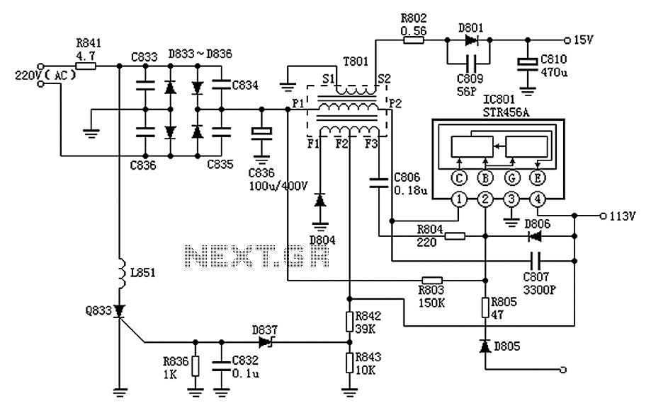
The Panasonic M12H switching power supply circuit is utilized in Panasonic models such as TC-230H, TC-2030DHN, TC-830D, and TC-840D. The circuit operates with an oscillation frequency that generates approximately 300V DC voltage at C836. The T801 transformer is involved...
A Common Cathode LED strip is being utilized instead of a Common Anode variant, leading to the development of a modified circuit. The experience with FETs was limited, resulting in challenges as a minimum voltage equal to Vcc is...
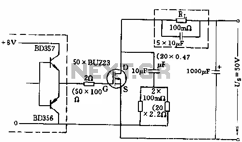
The circuit employs 50 BUZ23 field effect transistors (FETs) arranged in parallel, with a tube blocking voltage of 100V. The control power required is minimal, eliminating the risks associated with second breakdown and the positive temperature coefficient phenomenon in...

The LA1070 is an automatic gain control integrated circuit designed for use with automotive on-glass antennas. It is produced by Sanyo Semiconductor Corporation. The LA1070 operates by automatically adjusting the gain of the antenna signal to maintain a consistent output...
The circuit is designed for sound and light control of stairway and walkway lighting. It features high immunity and includes soft-start and over-current protection mechanisms. During the day, the photosensitive resistor has low resistance, resulting in a low voltage...
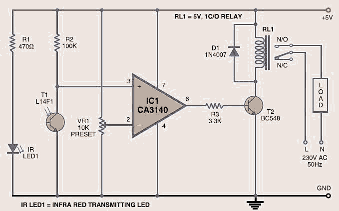
The wireless light switch circuit described here requires no physical contact for operating the appliance. You just need to move your hand between the infrared LED (IR LED1) and the phototransistor (T1). The infrared rays transmitted by IR LED1...