
Writing text on LCD Module using 89C51

The LCD module operates as a crucial component in various electronic applications, often interfacing with microcontrollers for display purposes. The configuration of the Command Register at address 00H allows for the execution of specific commands such as clearing the display, setting the cursor position, and adjusting display settings. The Data Register, set at address 01H, is essential for sending ASCII characters to be displayed on the screen.
In the implementation, the Octal Latch 74573 serves as a buffer to manage the data and address lines efficiently, ensuring that the microcontroller can communicate effectively with the LCD module. The use of Port "0" for both address and data lines simplifies the connection, allowing for a more straightforward design.
The initialization subroutine is a critical part of the program, as it prepares the LCD module for operation by configuring its settings and ensuring that it is ready to receive commands and data. The provided C library enhances the usability of the LCD by offering pre-defined functions that abstract the complexity of direct register manipulation, allowing developers to focus on higher-level programming.
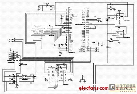
The availability of the PCB layout and example program facilitates rapid prototyping and development, enabling engineers to implement the LCD module in their projects with ease. By following the guidelines and utilizing the provided resources, the integration of the LCD module into various applications can be achieved efficiently and effectively.In the circuit shown below i have configured the LCD module Command Register at address 00H and Data Register at 01H, so when ever we will write the data at address 00H, it will be considered as command for LCD, and when ever at 01H, it will be considered as ASCII character to be write. the following table shows addresses for different read write operations. To use the LCD module as memory mapped i/o as explained above we will have to do the following connections with micro controller, since the address and data both will transfer through Port "0", therefore we will have to use an Octal Latch 74573. the PCB layout is also available to download. an example program is also available to download, Here i have given different subroutines, by combining which we can make a complete program, first of all i will show you the subroutine for initialization of LCD module.
I have also written a library in C Language, by which we can write any type of data on LCD using C language, there are many built in functions which can be called from any "KEIL C" program, and all necessary files including that library can be download from the link given below. 🔗 External reference
Related Circuits
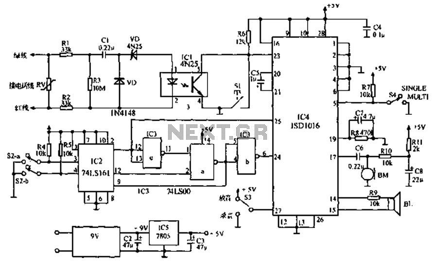
The call is made using the ISD1016 language chip for voice generation instead of a traditional phone ringing message controller schematic circuit. This controller can store messages, music, songs, or other sounds, serving as an alternative to monotonous ringing. The...
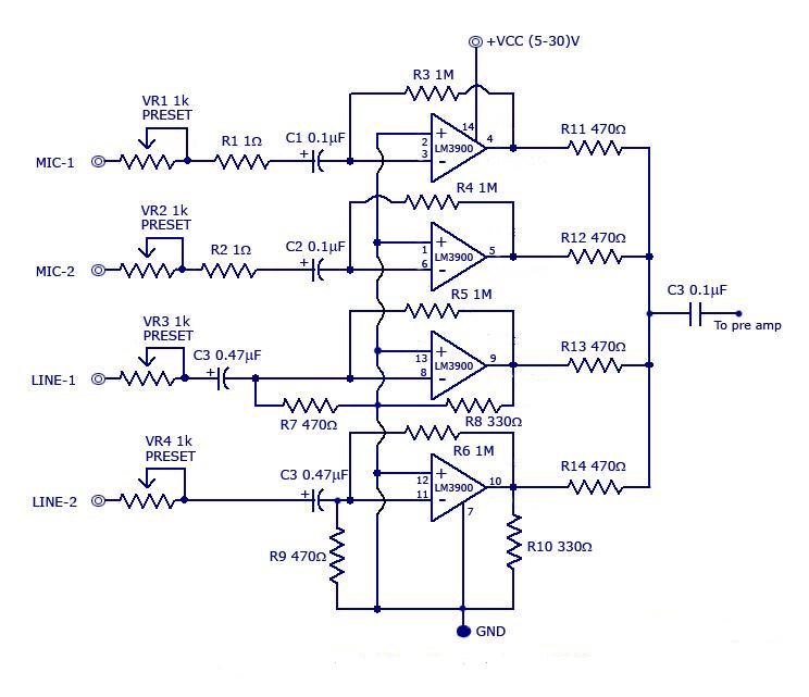
The circuit includes a quad channel amplifier (LM3900) with microphone audio inputs and direct line inputs. By adding circuits in parallel, the number of inputs can be increased for various applications. The input is connected to the inverting terminal...
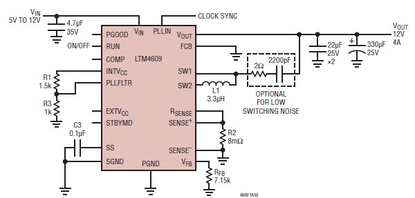
A very simple, high-efficiency switching mode buck-boost power supply circuit can be designed using the LTM4609 switching regulator IC. This circuit will provide a fixed output voltage of 12 volts. As illustrated in the schematic, the switching power supply...
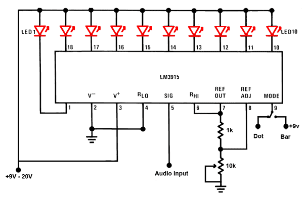
This is a simple audio sound level LED display circuit diagram. The circuit is entirely based on a single integrated circuit, the LM3915 from National Semiconductor. The LM3915 is a monolithic integrated circuit that displays the audio sound level...
Due to their speed, accuracy, effectiveness, and cost-efficiency, infrared (IR) digital thermometers have supplanted traditional mercury thermometers. An ear digital thermometer utilizes a thermopile sensor to measure the infrared heat emitted by the eardrum, which correlates with the temperature...
This text discusses the MSC1210 microcontroller as the core of a high-accuracy temperature measurement system, which includes signal processing and communication capabilities. The system is designed for easy expansion, allowing for accurate measurements and fast data acquisition. The hardware...