Toxic gas detector
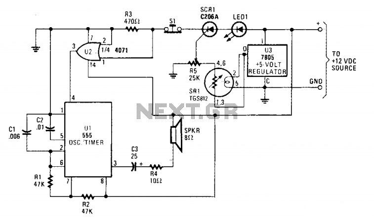
The primary component in the circuit is the SRI, a TGS812 toxic gas sensor produced by Figaro Engineering Inc. This gas-sensitive semiconductor functions as a variable resistor when exposed to toxic gases, resulting in a decrease in electrical resistance as gaseous toxins are absorbed by the sensor surface. A 25,000-ohm potentiometer (R5) is connected to the sensor, serving multiple roles: it acts as a load, creates a voltage-dividing network, and provides sensitivity control, with its center tap linked to the gate of SCR1. When toxic fumes interact with the sensor, the reduction in electrical resistance allows current to flow through the load (potentiometer R5).
The voltage generated across the wiper of R5, which connects to the gate of SCR1, activates the SCR, allowing it to conduct. Once SCR1 is conducting, it supplies a 1-volt supply for the semiconductor components of the TGS812, even though a 10-volt supply is recommended, which effectively reduces the standby current. A 7805 voltage regulator is employed to provide the necessary 5 volts for the heater and semiconductor elements.
The circuit leverages the properties of the TGS812 sensor to detect the presence of toxic gases, utilizing the SCR for efficient switching. The potentiometer (R5) is crucial for adjusting the sensitivity of the sensor, allowing for fine-tuning based on environmental conditions. The integration of the 7805 regulator ensures that the circuit operates within safe voltage levels, providing stable power to the heater and semiconductor elements, essential for the sensor's operation. The design emphasizes low power consumption, particularly during standby, while ensuring reliable detection of toxic gases. This configuration is particularly useful in safety applications where monitoring air quality and detecting hazardous gases is critical.The major device in the circuit is SRI (a TGS812 toxic-gas sensor manufactured by Figaro Engineering Inc.) The gas-sensitive semiconductor (acting like a variable resistor in the presence of toxic gas) decreases in electrical resistance when gaseous toxins are absorbed from the sensor surface. A 25,000 ohm potentiometer (R5) connected to the sensor serves as a load, voltage-dividing network, and sensitivity control and has its center tap connected to the gate of SCR1.
When toxic fumes come in contact with the sensor, decreasing its electrical resistance, current flows through the load (potentiometer R5). The voltage developed across the wiper of R5, which is connected to the gate of SCR1, triggers the SCR into conduction. With SCR1 now conducting, pin 1-volt supply for the semiconductor elements of the TGS812 in spite of the suggested 10 volts, thus reducing the standby current.
A 7805 regulator is used to meet the 5-volt requirement for the heater and semiconductor elements.
