
toy organ

The circuit operates using a simple design that incorporates a microcontroller or a tone generator IC, buttons, and resistors. Each button corresponds to a different frequency, which is determined by the resistor-capacitor (RC) timing circuit associated with each button. When a button is pressed, it completes the circuit, allowing current to flow and the tone generator to produce sound at the frequency set by the RC network.
In a typical configuration, the buttons are connected to the microcontroller's input pins, which are configured to detect the button presses. Each button press can be associated with a specific frequency value stored in the microcontroller's programming. The 1k ohm resistors in the circuit can be replaced with different resistor values to fine-tune the frequency output, allowing the user to create a more accurate musical scale.
The output from the tone generator can be connected to a speaker or an audio output jack for sound amplification. The circuit may also include a power supply section to ensure stable operation. Additional features, such as volume control or LED indicators for button presses, can enhance the functionality of the monophonic organ, making it more user-friendly and visually engaging.
Overall, this circuit provides a fundamental approach to sound synthesis in a monophonic format, suitable for educational purposes or as a foundation for more complex musical instruments.This circuit produces a tone according to the button being pressed. Only 1 button can be pressed at a time, that`s why it is called a monophonic organ. You can change the 1k resistors to produce a more-accurate scale. 🔗 External reference
Related Circuits
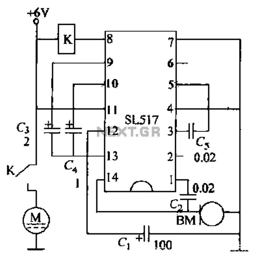
Electric cars utilize a voice circuit principle, where sound signals are captured by a microphone (BM) and processed. The signal is then coupled through a capacitor to an integrated circuit (IC), which includes an internal amplifier that boosts the...
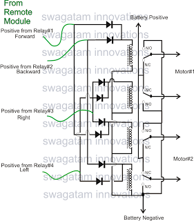
The market is filled with high-end remote-controlled toy cars; however, for hobbyists, creating one at home can be a unique experience. The following article explains how to configure a simple remote-controlled toy car using a pre-made 4-relay remote control...
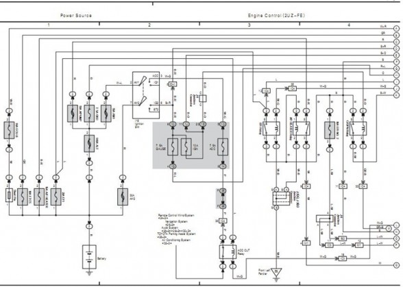
The following circuit illustrates the electrical circuit diagram for the 2006 Toyota 4Runner. It includes specifications related to the Toyota vehicle and details on safety features. The electrical circuit diagram of the 2006 Toyota 4Runner serves as a comprehensive representation...
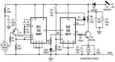
The following circuit illustrates an infrared toy car motor controller. This circuit is based on the 4047 and 4017 integrated circuits (ICs). Features: 16V. The infrared toy car motor controller circuit utilizes two primary integrated circuits, the 4047 and the...
This schematic illustrates a simple 555 organ circuit, which consists of two main components: the 555 timer circuit that generates tones and an LM386 amplifier for driving an 8-ohm speaker. The circuit produces slightly different tones when each switch,...
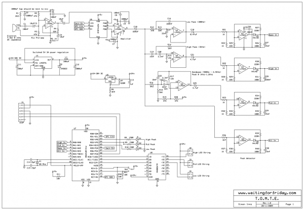
Most existing designs utilize direct switching of lights without any software control and include manual potentiometers for light sensitivity and overall gain settings. There are limited references regarding the frequency filter circuitry, explaining the specific frequencies the circuit is...