
2006 Toyota 4Runner Electrical

The electrical circuit diagram of the 2006 Toyota 4Runner serves as a comprehensive representation of the vehicle's electrical system. This schematic outlines various components such as the battery, alternator, fuses, relays, and wiring harnesses, providing a clear view of how these elements interact within the vehicle.
Key features of the circuit diagram include the layout of the power distribution system, which ensures that electrical energy is efficiently routed to different subsystems, including lighting, infotainment, and safety systems. The diagram also highlights the safety mechanisms integrated into the vehicle, such as airbag systems and anti-lock braking systems (ABS), showcasing how they are powered and controlled.
Additionally, the circuit diagram provides vital information regarding the specifications of the vehicle's electrical components, including voltage ratings, current capacities, and resistance values. This information is essential for troubleshooting electrical issues, performing maintenance, or making modifications to the vehicle's electrical system.
Overall, the electrical circuit diagram for the 2006 Toyota 4Runner is an indispensable tool for automotive technicians and engineers, facilitating a thorough understanding of the vehicle's electrical architecture and ensuring safe and efficient operation.The following circuit shows about 2006 Toyota 4Runner Electrical Circuit Diagram. Features: specs on Toyota car, and how the use of safety for .. 🔗 External reference
Related Circuits
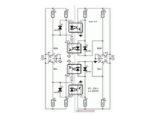
When the SDA (Serial Data) lines on both the left and right lines are high (logic level 1), the circuit remains in a quiescent state, and the optoisolators IC1 and IC2 are not activated. In this circuit, the Serial...
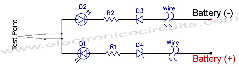
12V Vehicle Electrical Wiring Tester Circuit. This tester is useful for checking vehicle electrical circuits. Two LEDs indicate whether the circuit is live or not. The 12V vehicle electrical wiring tester circuit is designed to provide a simple yet effective...
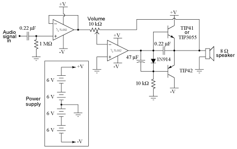
It is advisable to obtain TIP41 and TIP42 transistors, which are closely matched NPN and PNP power transistors with dissipation ratings of 65 watts each. If a TIP41 NPN transistor is unavailable, the TIP3055 (available from Radio Shack) serves...
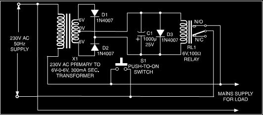
This is a low-cost protection circuit designed to safeguard electrically operated home appliances, such as TVs, DVD players, refrigerators, and other devices, during sudden power outages and the subsequent restoration of mains supply. Appliances like refrigerators and air conditioners...
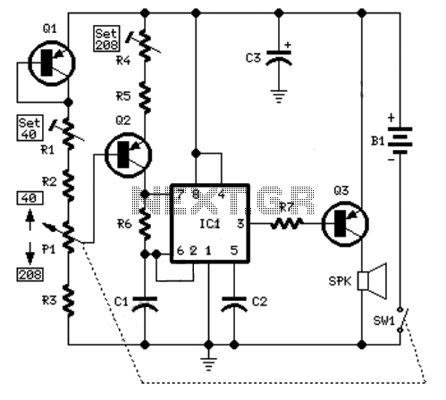
An example of an electronic metronome schematic is presented. The electronic metronome is popular due to its simplicity and compact size. The electronic metronome schematic typically consists of several key components that work together to produce a rhythmic sound at...
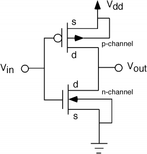
The fundamental issue presented is the perception that logic gates in a circuit seem to generate power from nothing, which contradicts the principles of physics. For instance, consider two NOT gates connected in series. It appears that the first...