
Traffic Signal Project

The proposed circuit design involves a power supply board capable of accepting a 120V AC input and converting it into multiple regulated outputs. The primary input will be connected to a transformer or a switching power supply module designed to handle 600 watts of power. This input stage will ensure that the board can safely manage the incoming voltage and current levels.
The output section will consist of at least three independent channels, referred to as outputs A, B, and C, each capable of delivering up to 200 watts at 120 volts. Each output will require individual regulation to maintain voltage stability under varying load conditions. This can be accomplished using linear regulators or switching regulators, depending on efficiency requirements and thermal management considerations.
To ensure safety and compliance, the design should incorporate circuit protection features such as fuses or circuit breakers on the input side to prevent overload conditions. Additionally, each output should include overcurrent protection to guard against potential short circuits or excessive load draws.
The layout of the board should facilitate adequate heat dissipation, especially near the voltage regulation components, as they will generate heat during operation. Proper thermal management strategies, such as heat sinks or active cooling solutions, may be necessary to maintain optimal operating temperatures.
Furthermore, appropriate filtering capacitors should be placed at the output terminals to minimize voltage ripple and provide stable power to connected devices. The overall design must adhere to relevant electrical standards and safety regulations to ensure reliable operation and user safety.
This schematic will require careful component selection, including transformers, rectifiers, capacitors, and voltage regulators, to meet the specified performance criteria while ensuring durability and reliability throughout its operational life.I would like to build a board that has 1 - 120volt/600Watt input and > 3 - 120volt/200Watt outputs. The outputs we shall call A, B .. 🔗 External reference
Related Circuits

The circuit diagram for the bridge integrated pressure signal conditioner MAX1450 is composed of various components. The MAX1450 is a high-performance integrated circuit designed for signal conditioning in pressure sensing applications. It is particularly suited for use with resistive bridge...
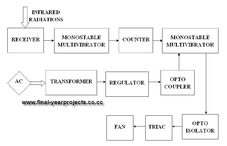
This report presents a comprehensive overview of a mini project titled "Remote Controlled Fan Regulator," developed in accordance with the curriculum requirements for the sixth semester of the Bachelor of Technology degree in Electrical and Electronics Engineering. The report...

A simple FM transmitter circuit can be designed using the MC2833 integrated circuit, which is intended for cordless telephones and FM communication equipment. It features a microphone amplifier, a voltage-controlled oscillator, and two auxiliary transistors. The final output frequency...
This article discusses various Teralab Electronics projects involving the 2N2222 transistor. The content is straightforward and informative. The components mentioned can enhance understanding of the projects detailed in this article. For instance, readers can find and purchase the 2N2222...

This project demonstrates the use of the 8051 microcontroller to generate PWM outputs for two separate channels. The PWM signals can control the phase angle of SCRs or TRIACs for power regulation of AC loads such as heaters, motors,...

To display an RF signal, connect LI to the transmitter and points A and B to the vertical plates of the oscilloscope. Adjust LI for minimum SWR and C3 for the desired trace height on the CRT. More: L2...