
Transformerless joule thief circuit

The described circuit operates on principles akin to those of a Joule Thief, which is a type of boost converter designed to extract energy from low-voltage sources. The use of two transistors instead of one allows for enhanced efficiency and improved performance, particularly in terms of switching speed and output voltage regulation.
In this configuration, the two transistors are typically arranged in a complementary push-pull configuration. This arrangement enables one transistor to conduct while the other is in the off state, effectively alternating between the two to maintain oscillation. The inductor plays a crucial role in energy storage and transfer, charging when one transistor is conducting and releasing energy to the output when the other transistor is active.
The absence of a transformer core simplifies the design, reducing component count and size, which can be advantageous in compact applications. The circuit's reliance on a single inductor means that careful attention must be paid to the inductor's specifications, such as inductance value and saturation current, to ensure optimal performance.
The circuit can be powered by a low-voltage source, such as a single-cell lithium battery or a pair of AA batteries, making it suitable for applications where energy efficiency is paramount. The output voltage can be significantly higher than the input voltage, allowing for the powering of devices that require higher voltage levels.
Overall, this circuit design exemplifies a minimalist approach to energy conversion, leveraging the properties of transistors and inductors to achieve efficient voltage boosting without the complexity of additional components like transformer cores.This is a circuit very similar to a Joule Thief, except that it is using 2 transistors, no transformer core, and only one inductor. 🔗 External reference
Related Circuits
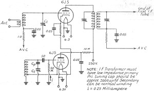
In 2011, designing a frequency converter circuit typically involves selecting an integrated circuit (IC) that meets specific requirements regarding gain and mixer spurious products, along with adding a couple of filters and a power supply. Often, the oscillator is...
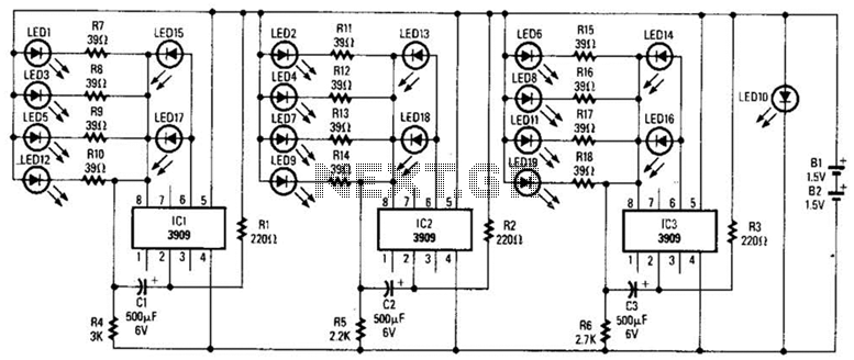
Three individual flashing circuits utilizing an LM3909 LED flasher/oscillator IC create the illusion of a pseudo-random firing order. The capacitors CX1, CX2, and CX3 control the blink rate, which ranges from 0.3 to 0.8 seconds. The wide tolerance range...
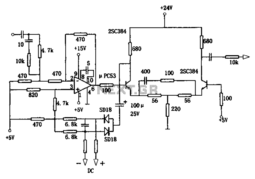
The circuit is designed for a broadband linear detection application with a bandwidth of 10 MHz. It serves as a millivoltmeter measuring instrument suitable for frequencies exceeding 10 MHz. The circuit features a linear detector utilizing operational amplifiers, specifically...
The welder no-load power saver circuit consists of a current detection control circuit and a power saving control circuit, as illustrated in the accompanying chart. The current detection control circuit includes a current transformer (TA), a bridge rectifier (UR),...
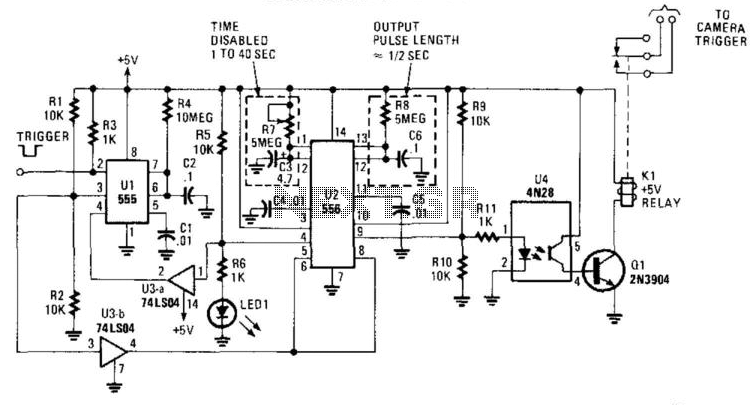
This circuit is designed to activate a camera shutter. Grounding pin 2 of U1 causes pin 4 of U1 to go high, which triggers both timers of the dual timer U1. One output maintains the reset (pin 4) of...

This article discusses a simple 5-channel radio remote control circuit utilizing the TX-2B and RX-2B integrated circuits from Silan Semiconductors. The TX-2B/RX-2B is a remote encoder-decoder pair suitable for remote control applications. It features five channels, a wide operating...