
Led Christmas Tree Light Flasher Circuit

The circuit design features three independent flashing circuits, each employing the LM3909 integrated circuit. This IC is known for its ability to generate a flashing effect in LEDs, and in this application, it is configured to create a visually appealing pseudo-random firing sequence. The blink rate is adjustable through three capacitors (CX1, CX2, CX3), which determine the timing intervals for the flashing LEDs. The selected values for these capacitors directly influence the frequency of the output, with a specified range between 0.3 and 0.8 seconds per flash. The variability in this timing is further enhanced by the inherent tolerance of the electrolytic capacitors used in the circuit, which can vary significantly, thereby introducing a degree of randomness to the flashing pattern.
The circuit consumes a continuous current of approximately 10 mA under normal operating conditions. However, it is important to note that if the values of resistors R4, R5, and R6 or capacitors C1, C2, and C3 are reduced to achieve a faster blink rate, the current draw will increase proportionally. This relationship between component values and current consumption must be carefully managed to ensure that the circuit operates within safe limits without overheating.
In terms of LED configuration, the design includes LEDs 13 through 18, which do not require external current-limiting resistors due to the built-in resistors within the LM3909 IC. This feature simplifies the circuit design and reduces the number of required components. LED 10, designated as the star of the display, is a unique flashing LED that operates at a fixed rate, providing a consistent point of light amidst the varying patterns of the other LEDs. This combination of features allows for a dynamic and visually captivating lighting effect suitable for decorative applications. Three individual flashing circuits that use an LM3909 LED flasher/oscillator IC create the appearance of a pseudo-random firing order. The combination of CX!RV C.JRb, and C^R control the blink rate, which is between 0.3 and 0.8 s, and the inherent wide tolerance range [-20% to +80%) of standard electrolytic capacitors add to the irregularities of the blink cycles.
The continuous current drain is about 10 mA; however, if you decrease the values of R4 through R6 or CI through C3 in order to increase the blink rate, the current will then increase proportionally. Note in particular that external current-limiting resistors aren`t needed for LED 13 through LED18; the resistors are built into the ICs. LED10, which serves as the tree`s star, is a special kind of flashing LED that blinks continuously at a fixed rate.
Related Circuits
The circuit is a battery charging system powered by Q2, Q6, R8, and D10, which provides constant current to charge the battery. When an external power supply is present, the charging current flows through R8 and D10 to charge...
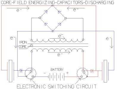
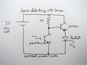
so what happens when you flip a switch? When you try to stop the flow of current in 'zero' time its equivalent to trying to stop a freight train instantaneously. you get a huge voltage buildup "dv/dt" = "X/0=infinity...
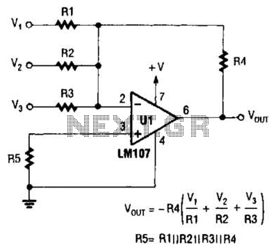
The output of Ul is the sum of Vv, multiplied by the ratio of Rx to Rv, RJRV, and respectively. Resistors R1, R2, and R3 are selected as required for individual gains. Additionally, R4 influences the gain of all...
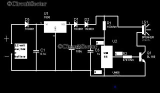
A simple musical horn circuit designed for use in cars or motorcycles can be connected to the 12V battery of any vehicle. This circuit is commonly utilized as a reverse musical horn. It employs the low-cost musical integrated circuit...
This circuit is a constant current protection type that limits the output current to a specific value in cases of over-current and short-circuit conditions. When the output current exceeds this limit, the output voltage decreases. The CW200 power management...
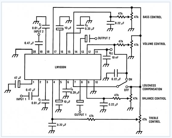
The LM1036 is a DC-controlled tone (bass/treble), volume, and balance circuit designed for stereo applications in car radios, televisions, and audio systems. It features an additional control input that facilitates loudness compensation. Four control inputs enable the adjustment of...