
transformerless low cost power supply

In a typical Capacitor Power Supply circuit, the design begins with the integration of an X Rated Capacitor (C1) in series with the AC mains line. This capacitor is specifically chosen to withstand high voltage spikes, ensuring reliability and safety. The reactance of this capacitor plays a vital role in determining the current flowing through the load. It is essential that the reactance is greater than the load resistance to maintain a stable current output.
When calculating the reactance, the frequency of the AC mains (usually 50 or 60 Hz) and the capacitance value are used in the formula provided. This allows for precise control over the expected current. For instance, with a 0.22 µF capacitor, the reactance is calculated to be approximately 14.4 kΩ, which would allow for a maximum current based on the mains voltage divided by this reactance.
The inclusion of a fuse (1A) serves as a protective measure against potential short circuits, while the MOV provides an additional layer of protection against transient voltage spikes that could damage other components in the circuit. The resistor R1 is strategically placed to limit inrush current during the initial power-up phase, preventing damage to the circuit components.
Following the capacitor, a bridge rectifier configuration using diodes (D1 to D4) converts the AC voltage to pulsating DC. Capacitor C2 acts as a filter to smooth out the rectified output, reducing ripple voltage. The Zener diode serves to regulate the output voltage to a specific level, ensuring that the connected load receives a stable DC voltage. Resistor R3 is employed to protect the Zener diode from excessive current, enhancing the reliability of the voltage regulation.
In the alternative design of a Resistive Transformer Less Power Supply, the circuit utilizes a resistive element to limit current instead of a capacitive reactance. This approach results in energy dissipation as heat, necessitating careful selection of resistor values to manage power loss effectively. The power dissipated across the resistor can be calculated, ensuring that the resistor is rated appropriately to handle the thermal load.
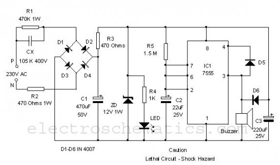
Safety precautions are paramount when working with these circuits. It is essential to avoid contact with any live circuit points and to ensure that the final assembly is housed in a properly grounded metal enclosure to mitigate shock hazards.In Capacitor Power Supplies we use a Voltage Dropping Capacitor in series with the phase line. An ordinary capacitor should not be used in these applications because Mains Spikes may create holes in dielectric of ordinary capacitors and the capacitor will fail to work. This may destroy the device by rushing current from the mains. Thus we use X Rated Capacitor with required voltage is used for this task. X Rated Capacitors rated for 250, 400, 600 V AC and higher are available. Reactance of the voltage dropping capacitor should be greater than the load resistance to keep constant current through the load. Where f is the frequency and C is the Capacitance. Thus a 0. 22G F capacitor has reactance of 14. 4KG © on mains frequency (50Hz). The approximate value of maximum current can be find out by dividing mains voltage byG‚reactanceG‚of the capacitor (since load resistance is small).
As shown 1A fuse may be used to avoid damages due to short circuit and a MOV ( Metal Oxide Varistor ) also may be connected as shown above to avoid problems due to voltage transients. The resistor R1 is used to limit the high current that may occur during power on. Capacitor C1 225K (2. 2G F) is used as the Voltage Dropping Capacitor. A Bleeder resistor is connected parallel to it for discharging the capacitor when the supply is switched off.
G‚Diodes D1 D4 is wired as Bridge Rectifier and the capacitor C2 is used to filter the pulsating DC. Zener Diode is used to regulate the filtered DC or you can use IC Voltage Regulator for better results. Resistor R3 is used to limit the current through the Zener Diode. Resistive Transformer Less Power Supply is similar to Capacitor Power Supply except that instead of Reactance it uses resistance to limit current.
Thus here excess energy is dissipated as heat across the Voltage Dropping Resistor. Care should be taken while selecting Voltage Dropping Resistor since the excess power is dissipated across it. Calculate power by multiplying Voltage and Current. P = VIG‚ Don`t Try this circuit if you don`t have much experience with electronics. Care should be taken while testing or using this circuit. Don`t touch at any points of the circuit since some points of this circuit is at Mains Potential. After constructing and testing enclose the circuit in a metal casing without touching PCB andG‚metal-case.
The metal case should be properly earthed to avoid shock hazards. G‚ 🔗 External reference
Related Circuits
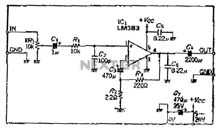
A closed-loop amplification circuit is designed to achieve a magnification of 100 times (40 dB). To ensure stable operation, particularly with high input signals, a variable resistor (VRi) is incorporated in the secondary circuit for attenuation. The feedback resistor...
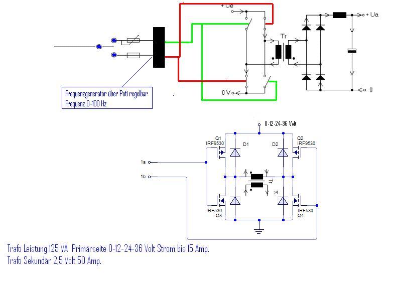
The simplest way to harness free available energy is by utilizing solar cells. A single efficient solar cell, when paired with a well-configured HHO generator, can produce a significant amount of gas suitable for various applications, all without incurring...
This is a simple power resumption alarm circuit that can be installed within the switch box. It emits beeping sounds when power is restored following a power outage. The power resumption alarm circuit serves as a practical solution for alerting...
This circuit illustrates the SSR (Solid State Relay) Power Control Unit Circuit Diagram. Features: The SSR control box supplies the control voltage for the relay. Component: . The SSR Power Control Unit Circuit is designed to provide efficient control of...
This circuit is a simple air flow detector that signals the presence of air flow. The sensor utilized is a filament incandescent lamp. Components include an air flow detector, a sensor, an LED, and an LM339 operational amplifier. The air...
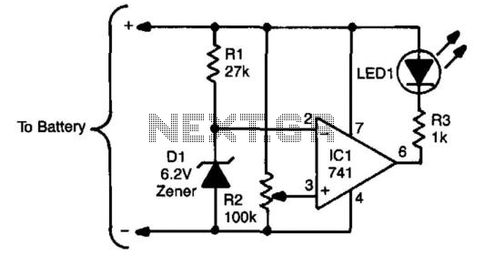
The sensing circuit consists of a 741 op-amp configured as a voltage comparator, utilizing a zener diode as a voltage reference. The op-amp is positioned as a bridge between two resistor ladders; one includes the zener reference, while the...