
Low-Battery Indicator

The described sensing circuit employs a 741 operational amplifier configured as a voltage comparator to monitor voltage levels. The circuit utilizes a zener diode to provide a stable reference voltage, ensuring accurate comparisons against the variable voltage from a high-value linear potentiometer. The potentiometer allows for fine-tuning of the input voltage, with the wiper providing a variable voltage that can be adjusted according to the application's requirements.
In operation, the circuit monitors the voltage at the potentiometer's wiper. When this voltage drops below the reference voltage set by the zener diode, the output of the op-amp switches to a low state. This output state is used to drive an LED, which indicates when the monitored voltage has fallen below the desired threshold. The LED is connected between the op-amp output and the positive supply voltage (Vcc), providing a visual indication of the circuit's status.
The design is versatile and can be adapted for various battery-powered applications. The voltage range of 6 to 18 V allows for flexibility in different systems, and the necessary modifications are straightforward. For applications operating below 9 V, a zener diode with a lower breakdown voltage should be selected, along with a corresponding current-limiting resistor to ensure proper LED operation without exceeding the current rating. Conversely, for higher voltage applications, a larger resistor must be chosen to limit the current appropriately, ensuring the longevity of the LED and the integrity of the circuit.
This sensing circuit is suitable for a wide range of applications, including battery monitoring, power supply regulation, and various safety systems that require voltage level monitoring and indication. Its simplicity and adaptability make it a valuable component in electronic design. The sensing circuit consists of a 741 op amp set up as a voltage comparator, using a zener diode as a voltage referen ce. The op amp is inserted as a bridge between two resistance ladders, one which contains the zener reference, and the other a high-value linear potentiometer. When the voltage at the wiper of the potentiometer drops below the voltage set by the zener, the output of the op amp becomes low; that turns on the LED connected between it and Vcc- The circuit can be adapted to work with battery-powered circuits that require between 6 and 18 V; the only changes needed would be a lower-voltage zener and a smaller current-limiting resistor in the case of voltage below 9 V, and a larger resistor for higher voltages.
Related Circuits
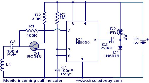
This circuit helps to avoid the annoyance of mobile phone rings while at home. It provides a visual indication when placed near a mobile phone, even if the ringer is turned off. When a call is received, the transmitter...
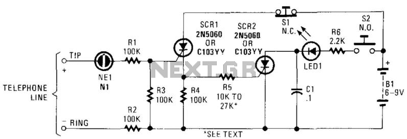
In this circuit, the ringing voltage on a telephone line causes NE-1 to break over, triggering SCR1, which in turn triggers SCR2. If a call has been received, depressing S2 will cause LED1 to light. Depressing S1 resets the...
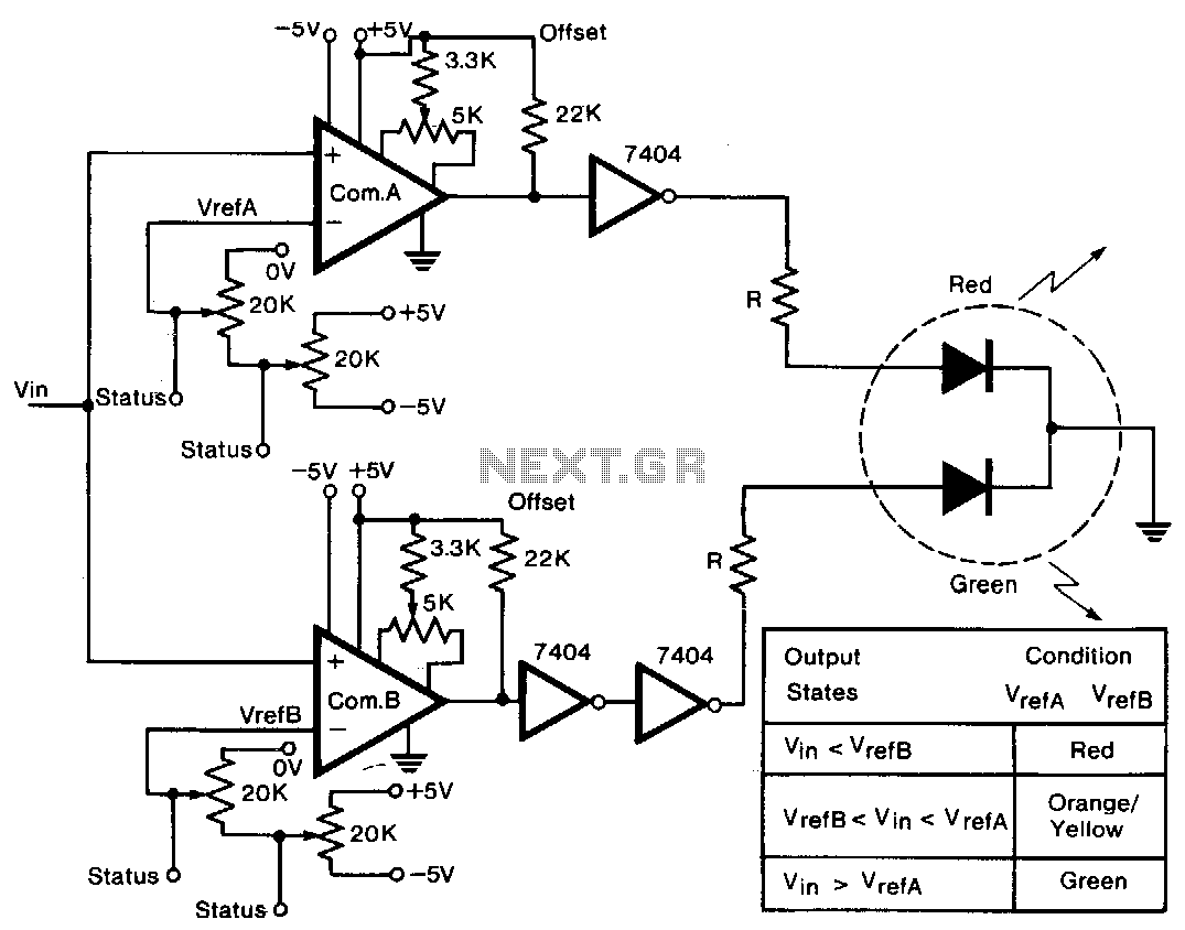
A tricolor LED serves as the visual indicator for voltage levels. The voltage to be measured is connected to two comparators in parallel. The first 20-KΩ trimmer sets a reference voltage between ±5 V, establishing the full-scale reference value....
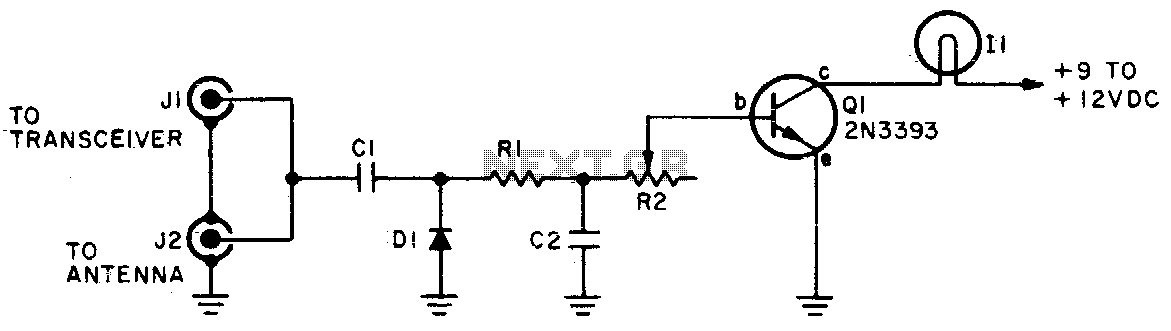
The brightness of the indicator lamp changes in accordance with the modulated RF signal. Adjust resistor R2 while the transmitter is on (modulated) until the lamp flashes in sync with the modulation. Cl = 5 pF, C2 = 100 pF,...
This circuit is designed to indicate the power output level of any audio amplifier. It is simple, portable, and displays three power levels that can be set to any desired value. For a standard HiFi stereo power amplifier, such...
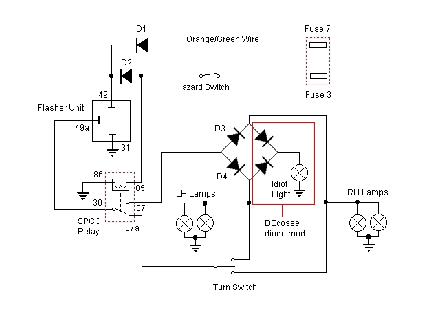
For some time, there has been a desire to incorporate a hazard flasher system into the Bonneville SE. After reviewing various discussions on this topic, a unique add-on system has been developed that functions correctly as hazard lights. This...