
Transistor Amplifier Circuit with Diagram for 12 Watts

This circuit is designed to amplify audio signals, making it suitable for applications such as driving speakers in a home audio system. The core component is a transistor, which operates in the active region to amplify the input signal. The circuit typically consists of a power supply, input coupling capacitors, biasing resistors, and feedback components that stabilize the gain.
The input audio signal is fed into the base of the transistor through a coupling capacitor, which blocks any DC component, allowing only the AC audio signal to pass. The transistor's collector is connected to the power supply, and the emitter is usually connected to ground through an emitter resistor, which helps in stabilizing the operating point and providing thermal stability.
An op-amp is utilized to achieve the desired gain. The op-amp configuration may be in a non-inverting or inverting mode, depending on the design requirements. Feedback resistors are employed to set the gain of the op-amp, ensuring that the output signal is an amplified version of the input. The output from the op-amp drives the base of the transistor, allowing for a significant increase in output power.
To ensure optimal performance, decoupling capacitors are placed near the power supply pins of the op-amp to filter out any noise. The output of the transistor can then be connected to a load, such as a speaker, where it delivers the amplified audio signal.
This 12-watt audio amplifier design is efficient and can be implemented on a printed circuit board (PCB) for compactness and reliability. Proper heat dissipation measures should be considered, as transistors can generate heat under load conditions. Overall, this circuit is a practical solution for audio amplification needs in various electronic projects.A simple transistor amplifier circuit diagram and schematic which can be used as a 12 watts audio transistor amplifier.An op amp IC is used to produce the gain required.. 🔗 External reference
Related Circuits
There was difficulty in understanding that the Source pin connects to low voltage (source of electrons) and the Drain pin connects to high voltage (absorbs electrons). This concept is fundamental to basic electricity, but it required some time to...
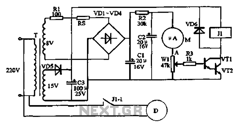
An automatic recording telephone interface circuit is presented, featuring an automatic answering and recording function that requires a reprovisioning or a small solid-state recording chip. The circuit is straightforward, with a quiescent current of less than 20 µA, allowing...
The quartz crystal oscillator circuit is highly advantageous in terms of frequency stability. Even the Voltage-Controlled Crystal Oscillator (VCXO) circuit, which allows for significant frequency changes, typically experiences only about a 1% variation. However, the linear range of control...
This is a good example preamplifier for microphones that can be used in mixing consoles. The circuit uses a dual op-amp, type NE 5532. The amplifier must be adjusted. This connect the power supply and control over P1 such...
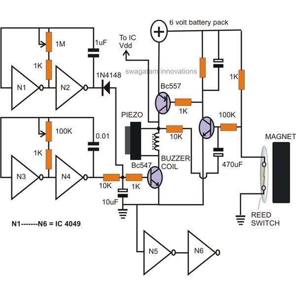
Certain circumstances and areas require the detection and securing of entrance paths through alarm systems, ensuring that whenever an individual opens an entrance door, the situation is instantly monitored by triggering an alarm. Battery-operated window and door alarms are...
An automatic humidifier can be utilized for humidity control in households, hatcheries, poultry farms, or juvenile poultry houses. When the humidity level falls below 50%, the automatic humidifier activates to maintain a specific humidity level that is beneficial for...