
Automatic recording telephone interface circuit

The automatic recording telephone interface circuit is designed to facilitate seamless interaction between a traditional telephone system and a recording device. The circuit's simplicity is one of its key features, enabling quick installation and integration without the need for extensive modifications to the existing telephone.
The use of an optocoupler (IC1) provides electrical isolation between the telephone line and the recording circuit, enhancing safety and reducing the risk of damage to sensitive components. The 4017 decimal counter/divider (IC2) plays a crucial role in monitoring the ringing signal from the telephone. It counts the rings and generates a high output signal after the fourth ring, which activates the recording function. This feature ensures that the device only engages when necessary, conserving power and extending the life of the recording chip.
The speech circuit (IC3) is programmed to respond to incoming calls when the owner is not available, allowing callers to leave messages. This function is vital for ensuring that important communications are not missed. The transformer design, with its specified winding configurations, is essential for proper voltage levels and signal integrity within the circuit. The choice of wire gauge for the windings affects the transformer’s efficiency and performance, contributing to the overall reliability of the recording interface.
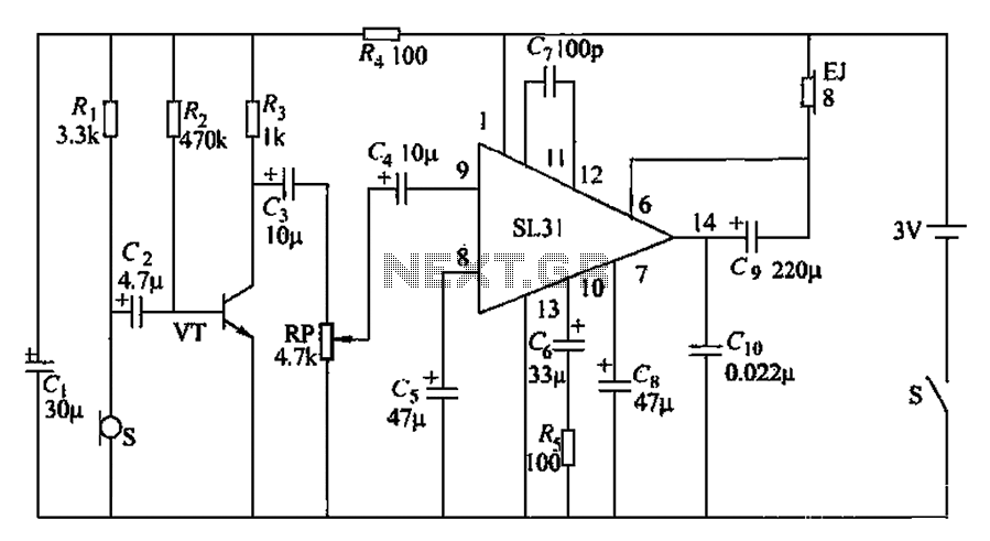
Overall, this circuit exemplifies an efficient solution for integrating recording capabilities into conventional telephone systems, providing users with a reliable method to capture messages without compromising the functionality of their existing telecommunication equipment. Automatic recording telephone interface circuit as shown, the circuit has an automatic answering and recording function (need to reprovision or small solid state recorder recor ding chip), the circuit is simple, the quiescent current of less than 20 A, an external lead connected to the external telephone without having to open the phone. IC1 is Optocouplers: IC2 (4017) decimal counter/divider, when the end of the fourth ring, ? feet high output behind the trigger circuit; IC3 speech circuit, there is not the owner, please brief leave a message.
Junior B with µ0.1mm wire around 350 turns, secondary winding enameled with µ0.07mm 1000 turns.
Related Circuits
Bicycle tire leak detector circuit schematic. The circuit detects air leaks in car tires caused by sharp objects. It uses a microphone (BM) to capture the sound of escaping air, which is then converted into an electrical signal. This...
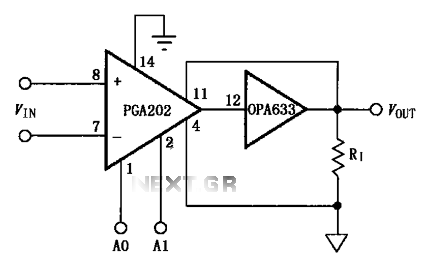
The figure illustrates a current boosting circuit configuration utilizing the PGA202 and OPA633 operational amplifiers. This circuit enhances the output current capability of the PGA202 operational amplifier, leveraging the performance characteristics of the OPA633 to achieve a higher output...
The following circuit illustrates a timer circuit with independent mark and space periods. It is based on the 7555 integrated circuit (IC). The high output duration is calculated by T(on) = 0.7 Ra Ct, while the low output duration...

A flashing LED indicates the need to water a plant in a 3V powered circuit. This circuit is designed to signal when a plant requires water. A LED flashes at a specified interval. This circuit operates on a 3V power...
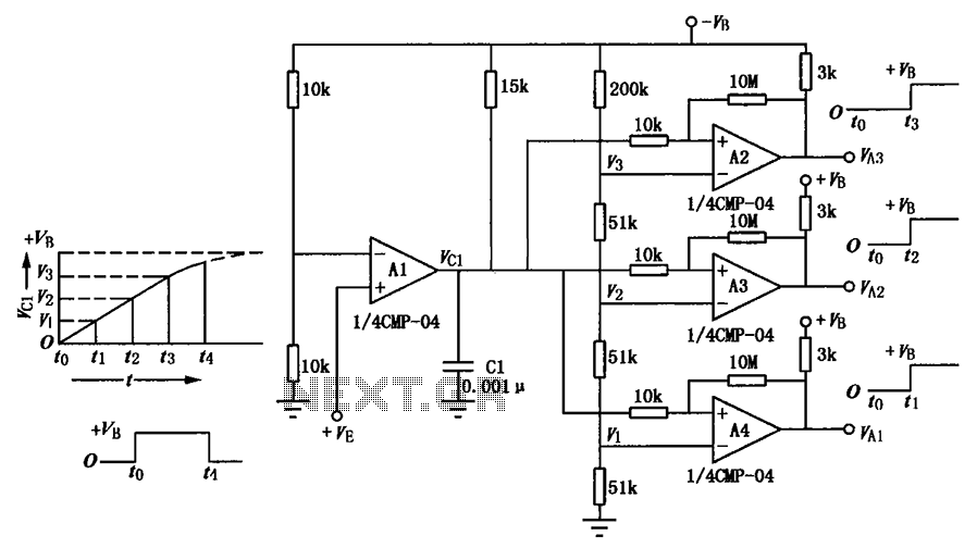
A multi-stage delay circuit is presented in this schematic. The operational amplifiers are configured as comparators. Operational amplifier A1 operates when the voltage at the inverting input exceeds + VE. As the voltage at the inverting input of operational...
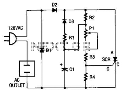
This circuit allows any standard household bulb to shimmer or blink. It is compatible with incandescent lights up to 200 W and operates on standard 120 Vac. The circuit employs a silicon-controlled rectifier (SCR) to create the shimmering effect....