
transistor based burglar alarm

The transistor-based burglar alarm circuit is designed to provide a reliable security solution for residential and commercial applications. The core of the circuit consists of a transistor acting as a switch, which is triggered by various input devices. The circuit is equipped with both exit and entry delays to allow users to safely enter and exit the premises without triggering the alarm.
The alarm system features two distinct zones: the "Exit/Entry" zone and the "Instant" zone. The Exit/Entry zone is designed to provide a delay, giving users time to leave the premises after activating the system. Conversely, the Instant zone is configured to trigger the alarm immediately upon detection of unauthorized entry, ensuring rapid response to potential threats.
For larger installations, the ability to add multiple zones enhances the versatility of the alarm system. Each additional zone can be configured to respond to various types of input devices, including normally-open and normally-closed switches. This modular design allows for tailored security solutions that can adapt to the specific layout and requirements of larger buildings.
User interaction with the system is straightforward. The presence of a green LED indicator provides a visual confirmation that the system is armed. The activation process is initiated by engaging switch SW1, which starts the exit delay. During this time, users must exit the building, after which the system becomes fully operational.
Upon re-entry, the buzzer serves as an audible warning, indicating that the user has a limited time to deactivate the alarm before the siren is activated. The alarm's design ensures that it remains vigilant, continuing to sound until the triggering conditions are resolved. The automatic reset feature further enhances usability, allowing the system to restore itself after a predetermined period if the situation is rectified.
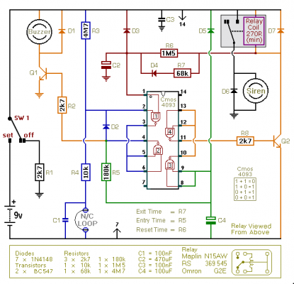
Adjustment of timing parameters is facilitated through the careful selection of resistor values. Resistors R2, R7, and R9 play a crucial role in determining the duration of exit, entry, and reset delays. By modifying these components, users can customize the alarm's response to fit their specific needs, accommodating variations in component tolerances and user preferences.
Overall, this transistor-based burglar alarm circuit is an effective and adaptable solution for enhancing security, providing users with flexibility and control over their alarm system.This is a simple transistor-based burglar alarm circuit. Its features include automatic Exit and Entry delays - together with a timed Bell cut-off and Reset. It`s designed to be used with the usual types of normally-closed input devices such as - magnetic-reed contacts - micro switches - foil tape - and PIRs. The basic alarm has an "Exit/Entry" zo ne and an "Instant" zone. This will be adequate in many situations. However - larger buildings are best divided into a number of smaller zones. The design allows you to Add As Many Zones As You Like to the basic system. They are "Instant Zones" - and may be triggered by both normally-open and normally-closed input devices. It`s easy to use. Make sure that the green LED is lighting - then switch the alarm on using Sw1. You have about 30 seconds to leave the building. When you return and open the door - the Buzzer will sound. You have about 30 seconds to switch off the alarm. If you fail to do so - the Siren will sound. While at least one of the trigger switches remains open - the Siren will continue to sound. However - if the trigger circuits have been restored - the alarm will reset itself after about 10 minutes.
Of course - you can turn the Siren off at any time by switching off the alarm. Because of manufacturing tolerances - the precise length of any delay depends on the characteristics of the actual components you`ve used in your circuit. But - to some degree - by altering the values of R2, R7 & R9 you can adjust the Exit, Entry and Reset times to suit your requirements.
Increasing the values increases the time - and vice-versa. 🔗 External reference
Related Circuits

A low-cost, high-performance programmable home security system utilizing a few LDRs as input sensors. When the sensors are triggered, the system can dial a user-specified phone number using a built-in DTMF generator and activate a high-power audio alarm and...
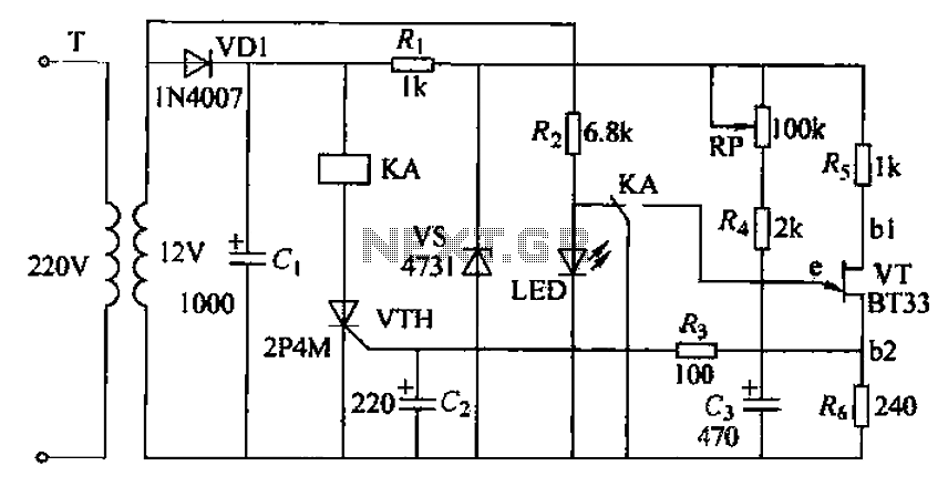
The circuit consists of a delay loop, discriminators, output circuits, power supply, and indicator lights, divided into five parts. The power regulation is achieved through a resistor (R), while the power regulator is constructed using a voltage source. In...
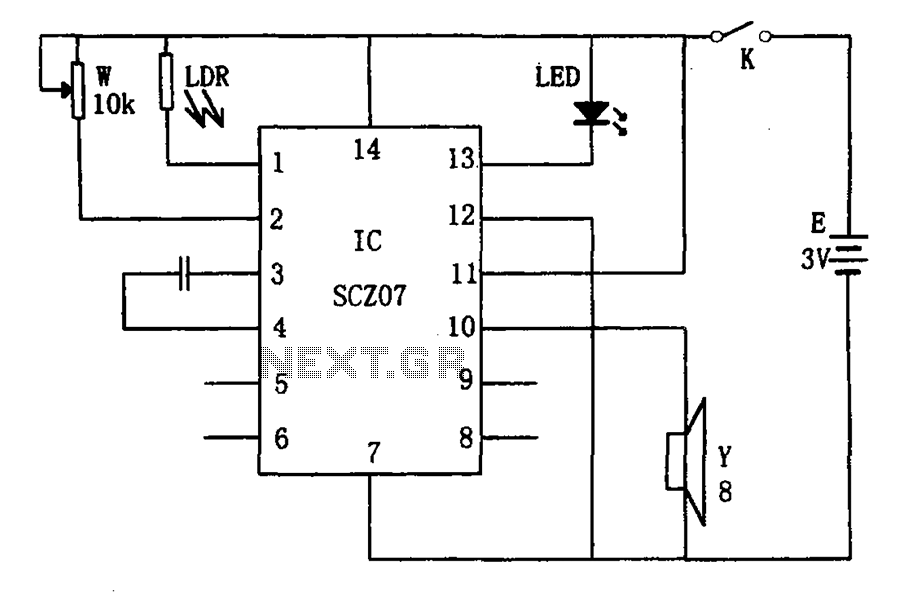
The weak light alarm circuit is illustrated in the figure. The oscillator circuit's core component is the SCZ07. The input signal is controlled by a potentiometer (W) and the output signal is processed by a photoresistor (LDR). The circuit...
A 30W Class AB power amplifier circuit diagram utilizes a power transistor. To set up the amplifier, adjust the variable resistor R1 to its maximum value and R12 to zero. After completing this setup, activate the amplifier. Adjust R1...
A simple, time-honored approach is to use one or more 74AC245 chips (normally the 74AC245 is used for maximum current capability) to provide motor drive current. Here, each channel of drive power is provided by one or more buffer...
This is an improved version of the basic Garage/Shed Alarm. The Entry and Exit delays have been extended to approximately 30 seconds, and a timed siren cut-off along with an automatic reset feature has been incorporated. Additionally, the LED...