
Weak light alarm SCZ07 a circuit diagram

The weak light alarm circuit utilizes an oscillator based on the SCZ07 component, which serves as the primary control unit for the entire system. The circuit operation begins with the adjustment of the potentiometer (W), which modulates the input signal fed into the oscillator. The photoresistor (LDR) detects ambient light levels, allowing the circuit to react accordingly. When the light intensity is at or above 100 lux, the resistance of the LDR is low enough to prevent the oscillator from triggering the alarm. In this state, both the speaker (Y) and the LED remain inactive.
As the light intensity drops below 100 lux, the resistance of the LDR increases, which in turn affects the oscillator's performance. The fine-tuning of the potentiometer (W) is crucial, as it sets the sensitivity of the circuit. By decreasing the resistance of the potentiometer, the circuit reaches a threshold where it can detect the lower light levels. This results in the activation of the oscillator, which generates a signal that drives the speaker (Y) to produce a beep sound, alerting the user to the low light condition. Simultaneously, the LED illuminates, providing a visual indication of the situation.
The design of this circuit is beneficial in environments where monitoring light levels is essential, such as in agricultural settings for plant growth or in security systems to detect unauthorized entry during low-light conditions. The adjustable sensitivity via the potentiometer allows for customization based on specific requirements, making the circuit versatile for various applications. Overall, the weak light alarm circuit effectively combines audio and visual alerts to ensure timely responses to changes in ambient light conditions. As shown in FIG weak light alarm circuit. The core of the oscillator circuit for the alarm SCZ07. Its input signal by the potentiometer W, control, output signal photoresistor LDR driven speaker Y, a light emitting diode LED work.When adjusting circuit is first placed in the maximum W position, LDR placed standard illuminance 100 lux, and the circuit can not afford to vibration, speaker Y does not sound. Fine-tune the W, so that the resistance from big to small, when adjusted to a certain value, start-up circuit, the speaker issued a beep.
sound, then W slightly recall some of the circuit just stop vibration, the alarm on a good tune.For this circuit, when the light is below standard illuminance (100 lux), the speaker issued a warning beep. sound, while the light emitting diode LED lights to show the light is dim. When light is greater than 100 lux, the alarm does not work, that the speaker does not sound, the light emitting diode does not shine.
Related Circuits
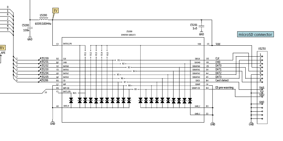
In this tutorial, the functioning of the memory card circuit in mobile phones will be explored. The previous post discussed the pin-outs and types of memory cards utilized in cellular devices. The accompanying block diagram illustrates how the removable...
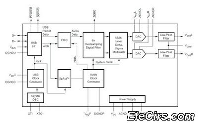
The USB sound card circuit utilizes the PCM2702 integrated circuit (IC) to create a fully functional USB sound card. The design is straightforward, allowing for the easy implementation of audio processing capabilities. The PCM2702 is a versatile USB audio controller...

Stepper motors are widely used in applications such as process control, machine tools, and robotics. In particular, remote control of stepper motors is essential in robotics and process control. This document provides the circuit diagrams for both the transmitter...
Standard LED flashers activate the LED in a rapid on-off sequence, which can become bothersome over time. The circuit presented here offers a more gradual illumination effect. This circuit utilizes a simple design to create a soft flashing LED effect,...
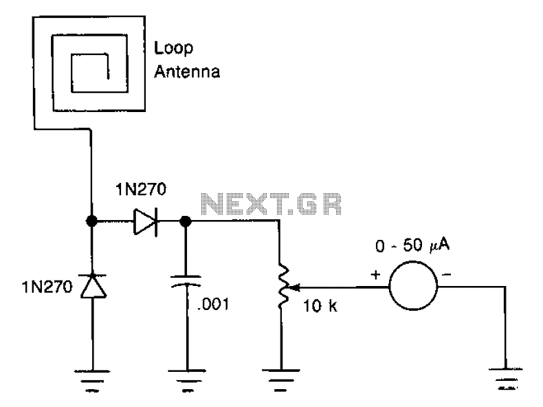
The antenna consists of approximately 20 cm of insulation made from strands, which are glued together inside a small plastic box. An RF current is processed through two diode rectifiers, and a 10k potentiometer is connected to the pin...
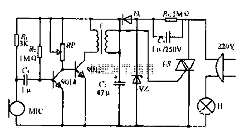
22W by Ct and R, RC Buck, rectified by n. c, filtering. vz 3V DC regulated output power, before U, V2 and MIC power supply. When the audio signal reaches the beam, the microphone MI converts acoustic energy into...