
Programmable Home Security Alarm System

This programmable home security system is designed to provide effective monitoring and alerting capabilities in residential settings. The system's reliance on LDRs as sensors allows for light-sensitive detection, making it suitable for detecting unauthorized entry during low-light conditions. The integration of a DTMF generator enables the system to communicate with the user via telephone, providing real-time alerts that can be crucial for prompt response.
The choice of components reflects a balance between performance and cost-efficiency. The PIC16F877A microcontroller serves as the core processing unit, managing inputs from the sensors and controlling output functions. The LM339 comparator is utilized for sensor interfacing, allowing for precise detection of light levels and triggering the alarm system accordingly. The UM3561 tone generator provides audible alerts, with selectable tones enhancing the system's versatility in alarm signaling.
Power management is effectively handled by the LM series voltage regulators, ensuring stable operation across the various components. The PCB design is critical, as it not only facilitates assembly but also ensures safety by isolating high-voltage components from user-accessible areas.
The RS232 interface is an essential feature, providing a user-friendly method for configuration and monitoring. Users can navigate through menus to adjust settings, conduct self-tests, and generate reports, thereby enhancing the overall usability of the system. The inclusion of a reset switch adds a layer of control, allowing users to quickly disable the alarm if necessary.
Overall, this home security system exemplifies a well-thought-out design that emphasizes reliability, user interaction, and effective monitoring, making it a valuable addition to any home security strategy.A low cost high performance programmable home security system using few LDR`s as an input sensors. When above sensor(s) get triggered system may dial the user specified phone number (using build-in DTMF generator) and activate the high power audio alarm and lights. All the parameters of DTMF generator, audio alarm and light interface are programmed through the RS232 serial interface.
Current firmware of this system presents interactive control system through the RS232 interface. This control system consist with the menu driven configuration options, self tests, system report generators, etc. This system also contain 5W (with 4 © speaker) audio alarm with three selectable tone configurations, which include Police siren, Fire engine siren and Ambulance siren.
his system uses a Microchip`s PIC16F877A as a main controller, LM339 as sensor interface, UM3561 as a tone generator and PC2002 as a speaker driver (audio amplifier). LM7805, LM7812 and LM317 voltage regulators are used to obtain +5V, +12V and +3V respectively. The PCB design given with this article makes the assembly much simpler. As PCB contain 230V AC main lines care must be taken while assembling the circuit. As shown in the fig all the photoelectric sensors, some of the switches and alarm speaker are connected with the circuit through the connector bars.
PHONE/LINE connector : Attach standard RJ12/RJ11 telephone cable connector to this port. One port is need to use with the phone line and remaining port is for the phone (and it is optional). Reset Switch : Press this button to reset entire alarm system. This button enable only when the audible alarm get activated. It is not possible to use this function at the phone dialing/ringer states. 6. If all the above Step 3, 4 and 5 are correct, disconnect the power supply and insert IC1, IC2, IC3 and IC4 in to the appropriate IC bases.
Attach suitable speaker to the X4 and connect RS232 cable to the system. PuTTY configuration setup for Programmable Home Security Alarm System * R6 X1 sensor sensitivity, R8 X2 sensor sensitivity, R4 sensor gain controller (Common mode) 🔗 External reference
Related Circuits
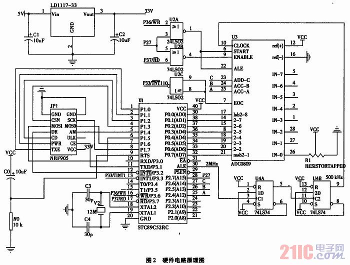
The technology of data acquisition is an important branch of information science. It is not only employed in intelligent instruments but is also widely used in modern industrial production and military science. This technology is essential for process control,...

The phase and neutral wires from the power source have already been connected to electrical appliances such as fans and light points. According to the UPS connection diagram, an additional phase wire should be connected to those appliances where...
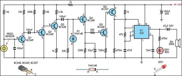
This circuit employs a thin piezoelectric sensor to detect vibrations caused by knocking on a surface, such as a door or table. It amplifies and processes the sensor's signal to trigger an alarm for a predetermined duration. The piezoelectric...
This circuit was designed to produce an audible alarm when the mains power is interrupted. Such an alarm is essential for anyone whose livelihood depends on continuous power supply. The circuit functions by monitoring the presence of mains voltage. It...
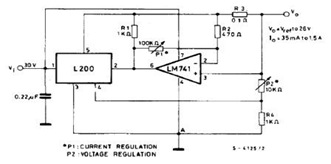
The datasheet contains application circuit diagrams for the L200, including a Programmable Voltage Regulator, a High Current Voltage Regulator with Short Circuit Protection, a Digitally Selected Regulator with Inhibit, a Programmable Voltage and Current Regulator, a High Current Regulator...
The system's block diagram illustrates the essential components for broadcast monitoring during a specified period. Key programs can be displayed based on the presence or absence of audio, utilizing a selected demodulator. An audio amplifier is integrated to provide...