
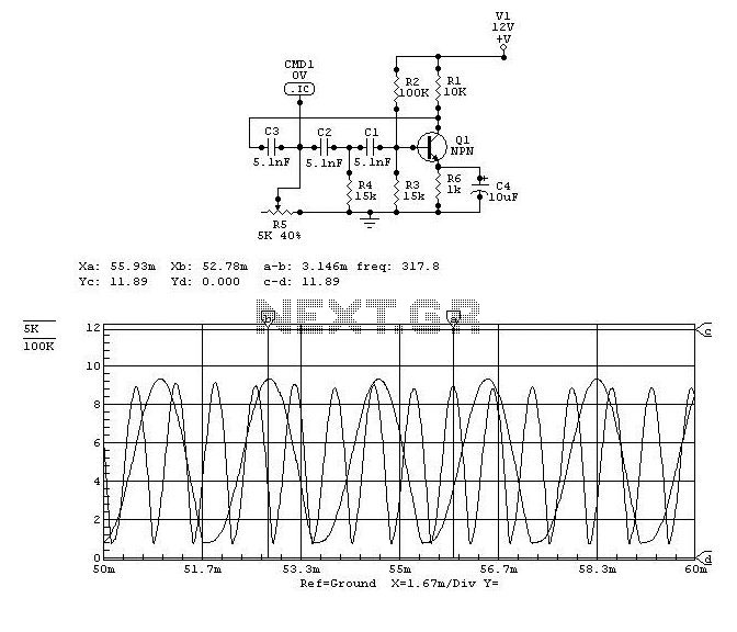
Transistor Class A Power Amplifier

In a Class A biasing configuration, the transistor operates in the active region for the entire cycle of the input signal. This ensures that the transistor remains in a conductive state, allowing for linear amplification of the input signal. The biasing is typically achieved by applying a DC voltage to the base terminal of the transistor, which sets the quiescent point (Q-point) at a level that allows the collector current to flow continuously.
The stability of the Class A biasing can be influenced by the resistor values used in the biasing network. Commonly, a voltage divider biasing scheme is employed, where two resistors are connected to the base of the transistor. This configuration helps maintain a stable Q-point despite variations in temperature or transistor characteristics.
In terms of operation, when an AC input signal is applied, it superimposes on the DC bias voltage. The resulting variation in base current causes the collector current to fluctuate correspondingly. This process allows for the amplification of the input signal while preserving its waveform.
The Class A amplifier is characterized by its high linearity and low distortion, making it suitable for high-fidelity audio applications. However, it is essential to note that Class A amplifiers are less efficient compared to other classes of amplifiers, such as Class B or Class AB, due to the continuous flow of current, which leads to greater power dissipation as heat. Proper heat sinking is often required to manage thermal performance in these circuits.
In summary, the Class A biasing of the transistor provides a reliable means of achieving continuous conduction, enabling effective signal amplification while necessitating careful consideration of thermal management and component selection to optimize performance.The transistor is biased in class A. That`s mean the collector current flows all the time. This current can increase or decrease, caused by the input signal.. 🔗 External reference
Related Circuits
This project was a surprise as the BC547 transistor (equivalent to 2N2222) can be used to construct a 500mW linear amplifier that operates across the entire HF band with excellent spectral purity and without the need for neutralization. The...
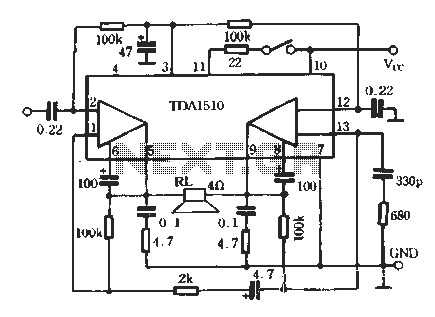
TDA1510 is an audio power amplifier from Philips. This integrated circuit (IC) includes features such as load short protection, open load detection, and an overheat protection circuit. It offers stable output voltage, excellent ripple rejection performance, requires fewer external...
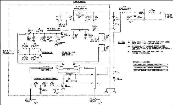
This article discusses a 2-meter amplifier capable of delivering an output of 25-30 watts. Over 35 units have been acquired at a cost of less than $50 each in bulk. Photo A displays the final version of the circuit...
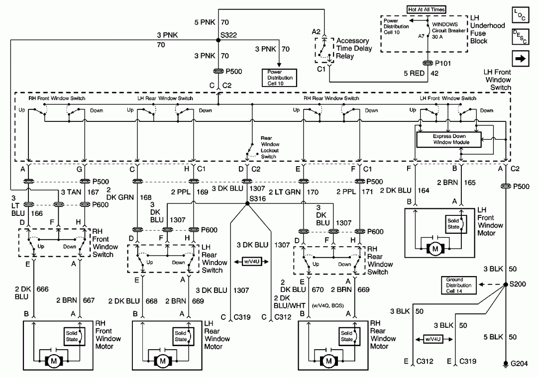
The system utilizes a single circuit breaker instead of fuses. According to the schematic, switches provide 12 volts of power and ground to the window motors in opposite polarities, allowing the windows to move up and down. Troubleshooting should...
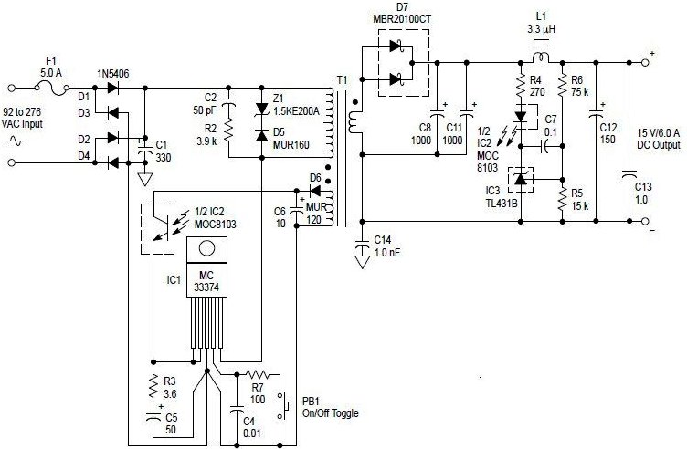
An AC to DC switching power adapter circuit with a maximum output power of 90W. The switching power supply is constructed using a high voltage power switching regulator IC, the MC33374, along with several additional components. The MC33374 IC...
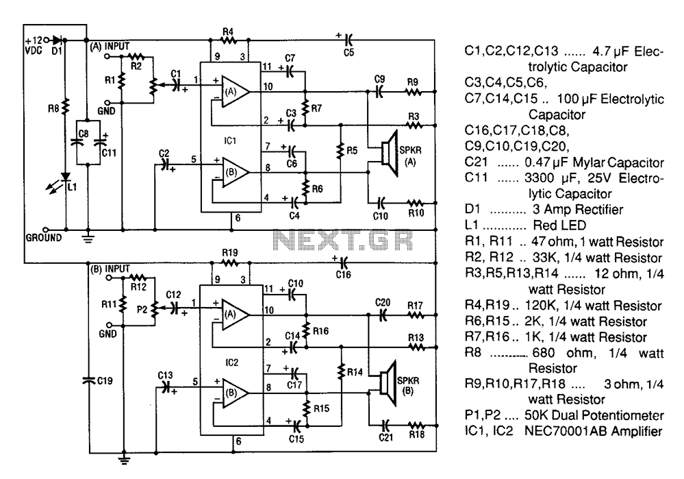
A 20W + 20W stereo amplifier comprises two independent 20-watt RMS amplifiers configured in a bridge arrangement. The input source is connected to a shunt voltage amplifier through resistors R1, R2, and potentiometer P1. Resistor R1 provides load resistance...