
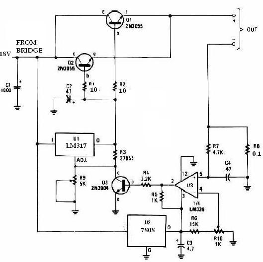
20W + 20W stereo amplifier circuit diagram

The 20W + 20W stereo amplifier operates by utilizing two distinct amplification channels, allowing for a robust audio output in a compact design. The bridge configuration of the amplifiers enables the combination of their output power, effectively doubling the power delivered to the load, which typically consists of speakers.
The input stage incorporates a shunt voltage amplifier, which is critical for signal conditioning. Resistor R1 serves as a load resistor to establish a reference point between the signal source and ground, ensuring that the input signal is appropriately biased for optimal performance. Resistor R2, in conjunction with potentiometer P1, allows for fine-tuning of the signal level before it is processed by the amplifier. This configuration is essential for managing the gain and ensuring that the input signal does not exceed the operational limits of the amplifier.
Capacitor C1 plays a vital role in coupling the input signal to the amplifier's internal circuitry. It blocks any DC component of the input signal while allowing the AC audio signal to pass through, thus protecting the amplifier from potential damage due to unwanted DC offsets. The internal amplifier IC1 amplifies the incoming audio signal at its (+) input (pin 1), significantly increasing the signal strength for further processing.
Capacitor C2, along with an additional capacitor connected to the ground, serves as a bypass capacitor, providing stability to the amplifier's power supply. This configuration helps to filter out noise and ripple from the power supply, ensuring that the amplifier operates efficiently and produces clean audio output. The overall design emphasizes the importance of component selection and layout in achieving high fidelity and reliable performance in audio amplification applications.20W + 20W of stereo amplifier consists of two complete, independent 20-watt RMS amplifier in bridge. The input source is brought into the shunt voltage amplifier, it is by R1, R2 and P1 thereof. Resistor R1 between the signal source and the ground provide a load resistance. Resistor R2 and potentiometer P1 binding signal. Signal through the same capacitor C1 and IC1 internal amplifier (+) input (pin 1) combined, where the signal is increased a lot. Capacitors C2 and other (B) of the internal amplifier IC1 (+) input to ground.
Related Circuits
The TDA2030 is a monolithic integrated circuit in a Pentawat® package designed to function as a Class AB audio amplifier. It typically delivers up to 14 watts of output power (with a distortion rate of 0.5%) at 14V with...
A magnetic switch is a circuit designed to respond to surrounding magnetic fields detected by the sensor. This series of magnetic switches employs limit switch sensors that include an additional metal plate capable of responding to a magnet. The...
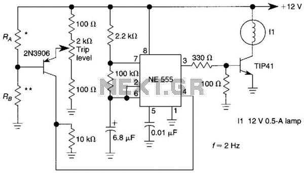
A sensor activates transistor Q1 to turn on the low-frequency 555 oscillator, which generates pulses to control LAMP II. The sensor may respond to variations in light or temperature. Either resistor RA or RB can function as the sensor,...
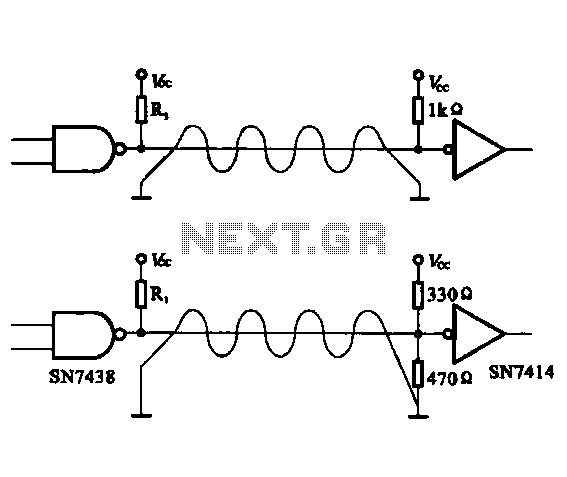
The circuit configuration for data signal output is designed to optimize transmission distance. It includes an output terminal connected to a pull-up resistor at the receiving end, which works in conjunction with two pull-up and pull-down resistors. The described circuit...
This universal battery charger utilizes the LM317 voltage regulator and features an adjustable output voltage along with a constant-current charging circuit, making it suitable for charging most NiCad batteries and various other battery types. The LM317 universal battery charger...
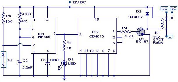
This simple circuit is started running by connecting a twelve volt battery across the terminals, causing the large diameter Light-Emitting Diode to light up. When the battery is removed, the LED stays lit up because the circuit has become...