
TRANSISTORIZED AM RADIO

The schematic of a typical transistor AM radio circuit primarily consists of several key components: an antenna, RF amplifier, mixer, local oscillator, IF amplifier, detector, and audio amplifier. The use of NPN transistors in this design allows for efficient signal amplification and processing.
The antenna captures the radio frequency signals and feeds them into the RF amplifier, which boosts the weak signals. The amplified RF signal is then sent to the mixer, where it is combined with a signal from the local oscillator to produce an intermediate frequency (IF) signal. This mixing process is crucial for demodulating the AM signal.
The IF amplifier further amplifies the intermediate frequency signal, enhancing the quality of the audio output. The detector circuit extracts the audio information from the IF signal, converting it back into an audible format. Finally, the audio amplifier increases the volume of the detected audio signal, allowing it to be heard through speakers or headphones.
Due to the generic nature of the schematic, component values such as resistors, capacitors, and inductors are not specified. This omission is intentional, as it encourages experimenters to modify and customize the circuit based on their specific requirements and available components. For those looking to build or experiment with an AM radio circuit, the schematic serves as a foundational guide, illustrating the essential stages of signal processing in a straightforward and accessible manner.Shown is a schematic of a typical transistor AM radio. This circuit uses npn transistors. The circuit is generic; therefore, no specific values are given for some components. This circuit is for ref-erence, to serve as a starting point for experimenters.. 🔗 External reference
Related Circuits
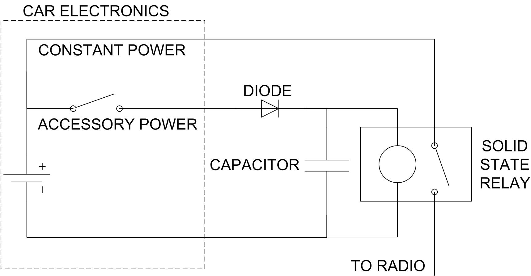
The car radio has the issue of losing track of the CD playback position when the ignition is turned off. This can be problematic during long journeys, especially when leaving an audiobook playing for passengers while refueling. A simple...
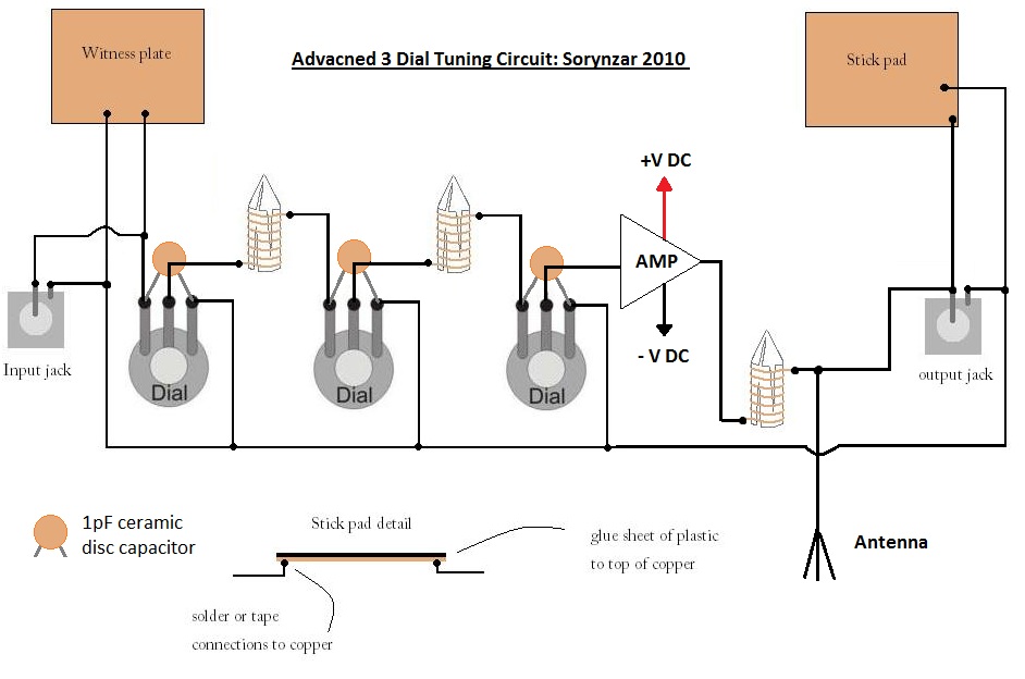
An advanced radionics schematic designed to enhance the power output of a tuning circuit. This schematic outlines a sophisticated approach to improving the efficiency and output power of a tuning circuit used in radionics applications. The circuit typically includes a...

The relay power in the linear circuit is derived from a -120 V bias supply, while the transmit keying output from the Kenwood device is +12 V with a maximum current of 10 mA. A critical component of this...
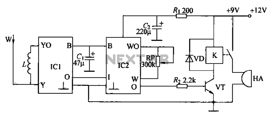
A circuit for an inductive burglar alarm is derived from a radio scanning detection circuit, which includes a signal processing circuit and an alarm circuit. The radar detection circuit module consists of components such as microwave emission, low-pass filtering,...
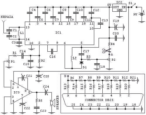
Stabilised tendency of catering: Vcc=9~12V. Frequency of reception: 88~108MHz. Consumption: 100mA. If you know some language of programming as C++, PASCAL, VISUAL BASIC, DELPHI etc you can write a program which will send in the parallel door (378 I)...
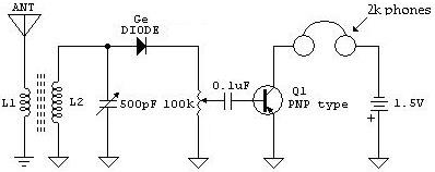
The following schematic illustrates a Crystal Radio Receiver Circuit Diagram that incorporates audio frequency (AF) amplification utilizing a Germanium transistor. The inclusion of AF amplification enhances the audio output quality. The Crystal Radio Receiver Circuit is a simple yet effective...