
Using Inputs

The described circuit leverages the capabilities of a microcontroller to create a simple yet effective digital input-output interaction. The 16F84 microcontroller is a popular choice for such applications due to its versatility and ease of use. The connection of switch SW1 to pin A0 allows for a straightforward method of detecting user input. When the switch is activated, it creates a low signal on pin A0, which the microcontroller reads as an event. This low signal serves as a trigger for the microcontroller to execute a predetermined response, in this case, turning on or off LED1 connected to pin B0.
In practical terms, the circuit can be implemented on a breadboard or a printed circuit board (PCB), ensuring that connections are secure and reliable. The use of a 32-kHz crystal oscillator provides a stable clock signal for the microcontroller, facilitating accurate timing and processing. If a microcontroller with an internal oscillator, such as the 16F818, is utilized, the design can be simplified by omitting the external crystal and capacitors.
The accompanying code, which is not fully included here, would typically involve initializing pin A0 as an input and pin B0 as an output. The main loop of the program would continuously check the state of pin A0. When a low signal is detected, the program would execute a command to toggle the state of LED1, providing visual feedback to the user. This basic control scheme can be expanded upon with additional logic, such as debouncing the switch input to prevent false triggering due to mechanical bounce.
Overall, this circuit serves as a foundational example of how microcontrollers can be used to create responsive electronic systems, integrating user input with output devices in a seamless manner.A control program usually requires more than turning outputs on and off. They switch on and off because an event has happened. This event is then connected to the input of the microcontroller to "tell" it what to do next. The input could be derived from a switch or it could come from a sensor measuring temperature, light levels, soil moisture, air quality, fluid pressure, engine speed, etc. In this chapter we will concern ourselves with digital on/off inputs. As an example let us design a circuit so that switch SW 1 will turn an LED on and off. The circuit diagram is shown in Fig. 11. 1. This circuit uses the 16F84 microcontroller with a 32-kHz crystal. It can of course also be performed with any of the microcontrollers discussed previously, including the 16F818 using its internal oscillator, in which case the crystal and 2 68pF capacitors are not required. In the circuit diagram SW1 is connected to A0 and LED1 to B0. When the switch is closed A0 goes low or clear, so we wait until A0 is clear. The code for this is: 🔗 External reference
Related Circuits
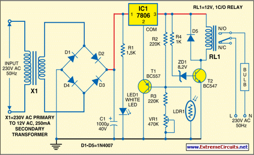
Voltage regulator ICs (78xx series) deliver a stable output voltage despite a fluctuating input supply when the common terminal is grounded. Any voltage above zero volts (ground) connected to the common terminal is added to the output voltage, meaning...

Explore the power amplifier integrated circuit from National Semiconductor, the LM4780. What is noteworthy about this component is its very low harmonic distortion. Typically, manufacturers specify the maximum power of their products with a harmonic content of around 10%....

An analog VU meter is commonly found in audio equipment to indicate signal levels in volume units. It features a peak LED and compares the response of the VU meter (represented by a black line) with the instantaneous input...

The LED flasher circuit operates by flashing an LED using only a 1.5-volt power supply. Typically, a power supply of more than 2 volts is required for an LED to function. The LED flasher circuit designed for operation at 1.5...
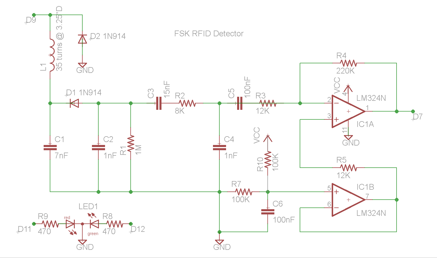
This document describes the construction of an RFID reader utilizing an Arduino (specifically tested with the Nano 3.0, although other models may also be compatible), a hand-wound wire coil, and various low-cost common components. RFID readers are devices manufactured...

The circuit diagram represents an ultra-sensitive intruder alarm. A shadow from an intruder passing nearby is sufficient to trigger the alarm. The operational amplifier IC2 (uA 741) is configured as a sensitive comparator, with its set point determined by...