
Using voice switch circuit relay lighting

The voice-activated relay control circuit is designed to provide a convenient method for controlling lighting systems through sound activation. The core component of this system is a relay, which acts as a switch that can be toggled on or off based on audio input received by the microphone.
The operation begins with the microphone detecting sound. The choice of microphone is flexible; options include a carbon microphone, a headset microphone, or a CR22-9 type condenser microphone. Each of these microphones has its own sensitivity and response characteristics, allowing for adaptability based on the specific application environment.
When the first clap is detected, the microphone converts the sound wave into an electrical signal, which is then processed by a sound detection circuit. This circuit typically includes an amplifier to boost the signal and a comparator to determine when the sound level exceeds a certain threshold, indicating a clap. Once this threshold is surpassed, the circuit sends a signal to the relay, closing the circuit and allowing current to flow to the load, thus turning on the lights.
Upon the detection of a second clap, the process is repeated, but this time the signal sent to the relay is intended to open the circuit, cutting off the current and turning off the lights. This two-step clap mechanism ensures that the lights can be easily controlled without the need for manual switches, enhancing convenience in residential settings, particularly in corridors where traditional switches may not be easily accessible.
The relay used in this application should be chosen based on the load specifications, ensuring it can handle the voltage and current requirements of the lighting being controlled. Additionally, proper isolation and safety measures should be implemented to protect the circuit from electrical surges and ensure reliable operation over time.
In summary, this voice-activated relay control circuit offers a practical solution for managing lighting through sound, utilizing a straightforward clap detection mechanism and versatile microphone options to suit various user needs.It uses a relay control. The voice switch is characterized by: when the first clap, then through the load (lights); when the second clap, cut off the load (lights off). It can be used to control lighting or residential corridor. Sensor (microphone B) may be a carbon microphone or headset microphone, tape recorder can also be used with CR22-9 type condenser microphone.
Related Circuits

The simple 4-digit converter circuit has an output count of 1, designed for a frequency range from f-IMHz to 10.000 MHz. All diodes used in the circuit are IN4146 "POLYSTYRENE" NPO. The circuit utilizes the LF398 at the input...

This is a simple circuit that can be used as a sequential signal light in automobiles. The circuit is based on two integrated circuits (ICs): a TS 555 CN CMOS timer IC and a CD4017 decade counter IC. The...
By utilizing a high-gain, high-impedance operational amplifier, it is possible to construct a long time delay circuit using a resistor-capacitor (RC) configuration, as it allows for high... An operational amplifier (op-amp) is a versatile component widely used in electronic circuits,...
This circuit also prevents the shutdown circuit of the IR2161 from operating in the normal way; therefore, an external SCR-based protection circuit needs to be added. The IR2161 is a high-voltage, high-speed driver designed for driving IGBTs and MOSFETs in...
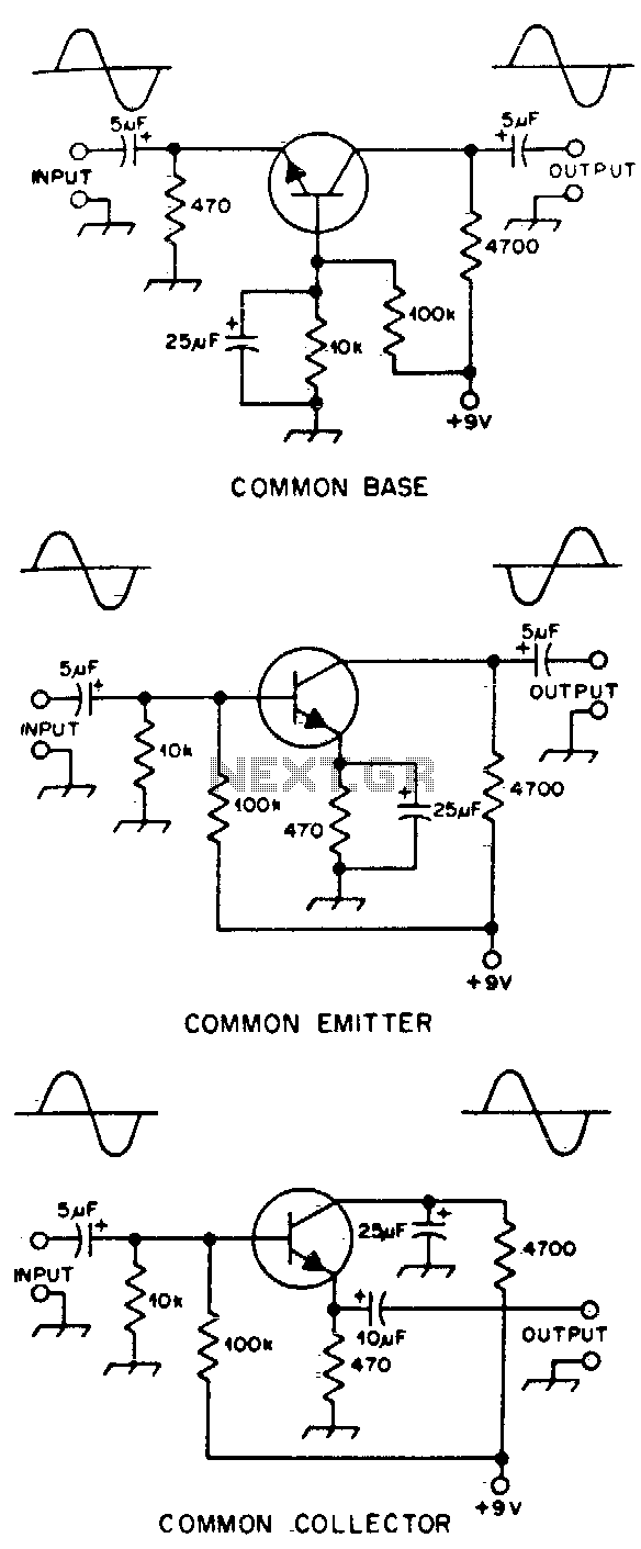
Typical component values are provided for use at audio frequencies, where these circuits are most commonly utilized. The input and output phase relationships are illustrated. The circuit design focuses on audio frequency applications, emphasizing the selection of component values that...

The circuit diagram illustrates a group of four analog electronic circuit switches (S1 to S4). Switches S1, S2, and S3 are utilized in a parallel delay circuit. When the power is activated, resistor R4 drives the triac VT, which...