
Transmission distance of 5m or less circuit configuration

The described circuit configuration facilitates effective data signal transmission over extended distances. The primary function of the output terminal, connected to a pull-up resistor, is to ensure that the signal level is maintained high when not actively driven low by the transmitting device. This is crucial in digital communication systems to prevent floating states that can lead to erroneous data interpretation.
In this setup, the pull-up resistor at the receiving end serves to establish a defined logic level when the line is idle. When a data signal is transmitted, the pull-down resistor can be used to pull the line low, ensuring that the signal is clearly interpreted by the receiving circuit. The combination of these resistors helps to create a stable environment for the data signal, minimizing the effects of noise and signal degradation over longer distances.
To enhance the performance of this circuit, careful selection of resistor values is essential. The pull-up resistor should be chosen to provide sufficient current to maintain the high state while minimizing power consumption. The pull-down resistor should be selected to ensure that the signal can be driven low quickly, allowing for high-speed data transmission.
Additionally, the layout of the circuit should be optimized to reduce capacitance and inductive effects, which can adversely affect signal integrity. Proper grounding and shielding techniques may also be employed to further improve transmission quality, especially in electrically noisy environments.
Overall, this configuration provides a reliable method for transmitting data signals over longer distances, ensuring that the information is accurately received and interpreted by the receiving device.Data signal output, transmission distance when Sm the following circuit configuration may be employed as shown, the main measure is the output terminal of the pull-up resistor at the receiving end of two pull-up and pull down resistors.
Related Circuits
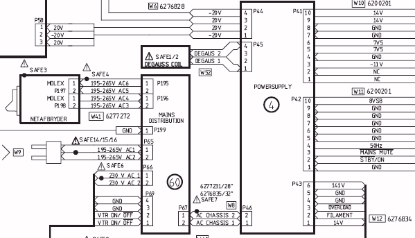
The AVANT employs a Switched Mode Power Supply (SMPS), which is centered around a 32 kHz ramp oscillator. This oscillator ceases operation if the overload protection circuit identifies an overload condition. When the oscillator is inactive, the 8-volt standby...
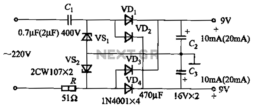
The circuit's output current capacity is influenced by the bulk capacitor Cl. When the capacitance of Cl is changed from 0.7 µF to 2 pF, the output current can be increased from approximately 10 mA to around 20 mA,...
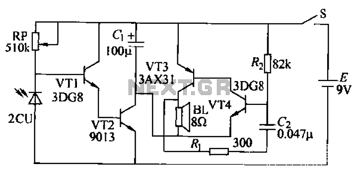
The core of the circuit is a two-transistor flasher with frequency modulation applied to the base of the first transistor. When the pushbutton is pressed, the oscillation frequency increases to a peak, and upon release, the frequency decreases due...
Boiling water or cooking with a gas stove can sometimes lead to the fire being extinguished due to water spills, which can result in a significant gas overflow and pose a risk of poisoning. This example describes a stall...
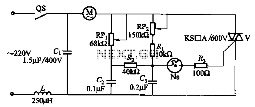
The 3P10 circuit, illustrated in the figure, utilizes a bidirectional thyristor for control. The adjustment potentiometer RPi allows for modification of the minimum motor speed, while the adjustment potentiometer RP2 enables continuous variation of the motor speed, reaching up...
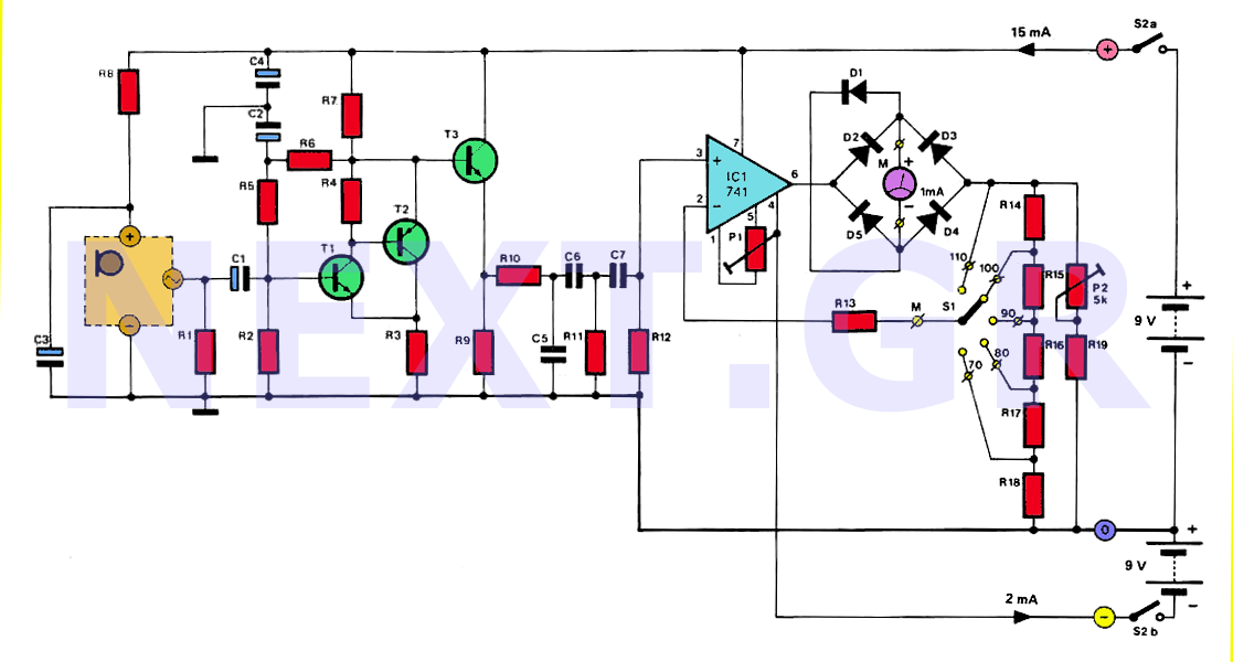
The human ear can detect sounds ranging from 20Hz to 20KHz, with the normal range typically between 100Hz and 13KHz, depending on an individual's age and health. For accurate measurements, a range of 20Hz to 20KHz is used. Sounds...