
AVANT Power Supply circuit

The Switched Mode Power Supply (SMPS) in the AVANT television operates on the principle of efficiently converting electrical power using high-frequency switching. The core component, a 32 kHz ramp oscillator, generates a square wave signal that drives the power supply's switching transistors. This process allows for the regulation of output voltage with minimal energy loss, making it suitable for compact electronic devices like televisions.
In the event of an overload, the protection circuit is designed to monitor the output and shut down the oscillator to prevent damage to the power supply and connected components. The absence of the 8-volt standby voltage indicates that the system is in a protective state, which prevents the standby light from illuminating.
To diagnose the issue effectively, it is crucial to differentiate between a genuine failure of the power supply and a fault elsewhere in the television that triggers the overload protection. The recommended approach involves measuring the voltage at the power supply board's connector P46. This connector is critical as it links the power supply to the rest of the television circuitry. By checking the voltage across pins 1 and 2 of P46, one can ascertain whether the power supply is functioning correctly or if the overload protection has been activated due to an internal fault.
Precautionary measures should be taken during this testing to ensure safety and prevent further damage. It is advisable to use insulated tools and, if necessary, to have a qualified technician perform the checks to avoid electrical hazards.The AVANT uses a Switched Mode Power Supply which means the heart of it is a 32khz ramp oscillator which is stopped if the overload protection circuit detects an overload. Without the oscillator running the 8 volt Standby voltage is not generated and is why your red standby light is not on.
We first need to establish if the situation is because of an actual power supply failure or an overload somewhere in the TV which is shutting down the power supply through the overload protection. This is best done at the connectors on the power supply board and below is a block diagram showing the connectors involved.
Check the power at P46 between pins 1 & 2, be very careful 🔗 External reference
Related Circuits
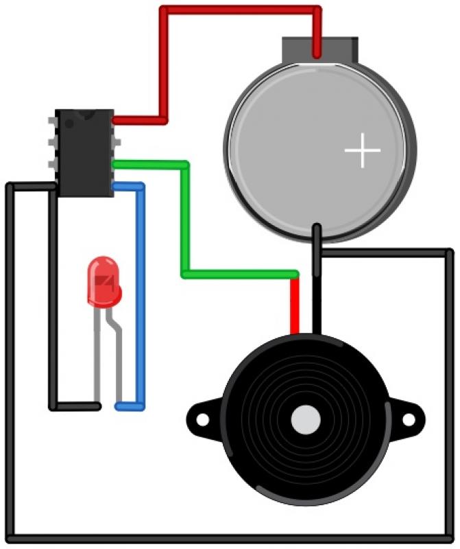
The Morse Beepy is a circuit designed to be simple and affordable, making it suitable for both children and adults as an introductory soldering project. It can be assembled and programmed within fifteen minutes to beep and blink a...
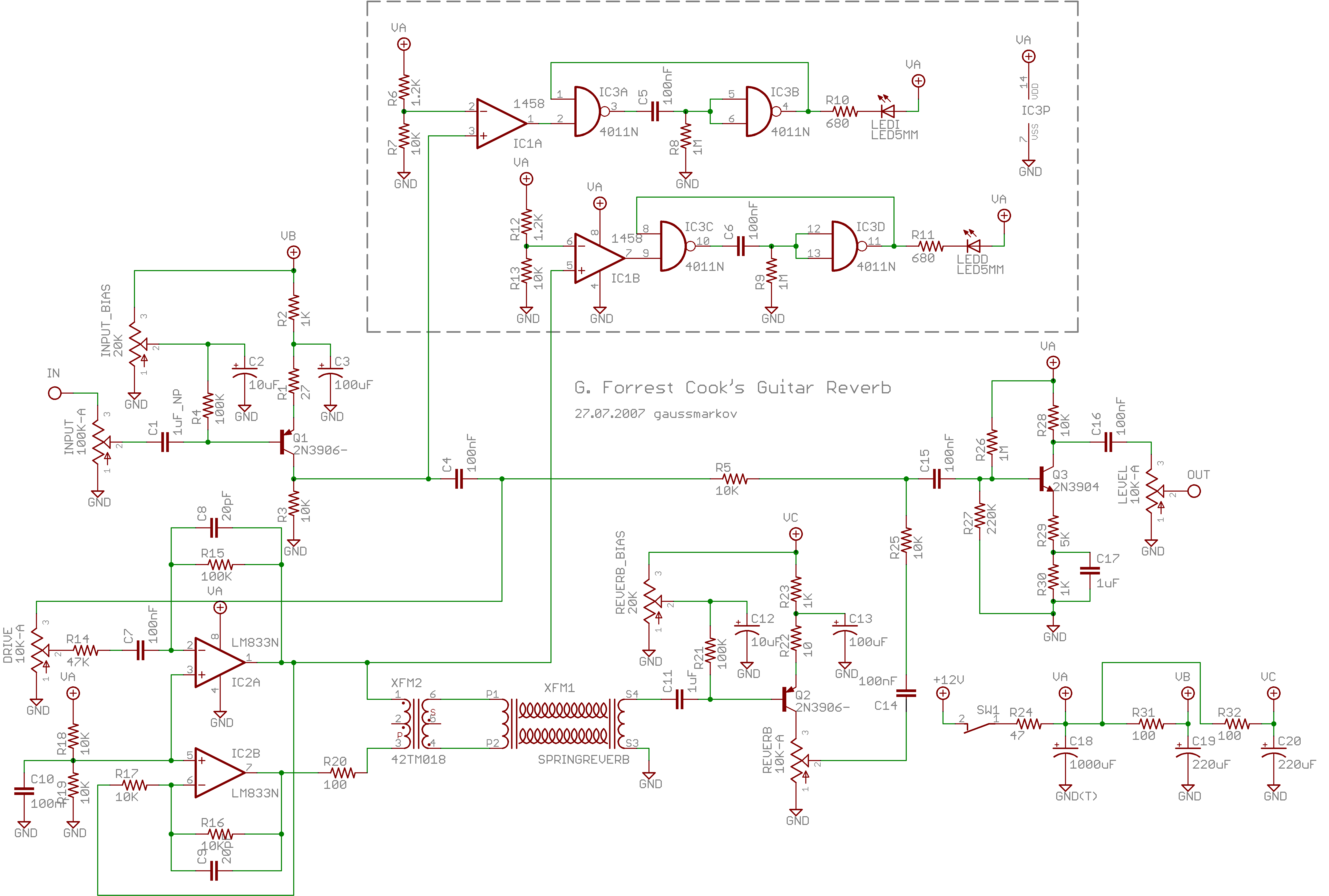
Spring reverb produces a clean and natural sound, often perceived as exceptionally good for a spring reverb. However, when the reverb springs are struck forcefully, they create explosive dub-like effects. Spring reverb is an analog sound processing technique that utilizes...
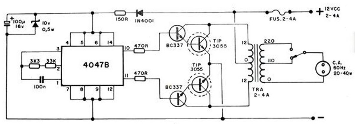
The converter transforms 12 VDC to 220 VAC, allowing for the conversion of 12 volts DC into 220 volts AC. The circuit diagram provided illustrates a simple converter circuit. This DC to AC converter can supply voltage for a...

The circuit connection is illustrated in figures a and b. In figure a, a star-shaped winding is used with shunt capacitance, while figure b depicts a triangular winding with capacitance connected in parallel. The working capacitance (Cc) is calculated...

Figure 4-7 illustrates the pitch analysis based on the relationship derived from the design calculation of the control circuit. In this setup, Ai serves as a buffer for the large stage, thereby alleviating the load on the preamplifier output....
A voice sound recording circuit is desired, which, when triggered, will play the recorded sound through an amplifier circuit. The proposed voice sound recording circuit can be designed using a microcontroller or dedicated audio recording ICs, along with an amplifier...