
Wireless IR headphone transmitter

The wireless infrared headphone transmitter operates by converting audio signals into modulated infrared light signals. The audio input is connected to PL1, which serves as the input jack for audio sources. This signal is fed into the VCO section of the 4046 PLL chip, where it is frequency modulated. The VCO generates a signal that varies in frequency according to the amplitude of the audio input.
The output of the VCO is then used to control Q1, a switching transistor. This transistor acts as an electronic switch, allowing the modulated signal to drive two infrared LEDs. The modulation of the current through these LEDs corresponds to the audio input, resulting in an infrared light signal that carries the audio information.
The two IR LEDs are positioned to emit infrared light in a direction where the receiving headphones can capture the signal. The headphones contain a photodetector that demodulates the IR light back into an audio signal, allowing the user to hear the transmitted audio wirelessly.
This design ensures efficient transmission of audio signals over a short distance, making it suitable for applications such as home theater systems or personal audio devices. The use of infrared light for transmission provides a line-of-sight communication method, minimizing interference from other electronic devices.Wireless IR headphone transmitter. Audio input from PL1 frequency modulates the VCO section of a 4046 PLL chip. The VCO output drives Q1, a switching transistor. Q1 drives two IR LEDs. The. 🔗 External reference
Related Circuits

The three schematics illustrate three building blocks for a 10-meter SSB transmitter. These blocks can also be utilized independently as circuit modules for other transmitters. The VFO board incorporates an FET transmission oscillator, with the VFO signal being mixed...

4 Channel 433MHz Wireless RF Remote Control Kit with a range of 200 meters. This RF remote control offers an extended range of up to 200 meters (650 feet) and is versatile for controlling various devices. The 4 Channel 433MHz...
A highly effective 1-watt FM transmitter circuit that is easy to construct. The circuit consists of four transistors: one functions as a stable oscillator, followed by a buffer stage to maintain frequency stability during adjustments. Next is a resonance...
This project is used to communicate or transmit a text message from one place to another place through wireless. The text message is encrypted by using the Microcontroller and the encrypted message was transmitted through wireless. At the receiver...
Long-distance infrared transmitter circuit diagram. This simple circuit offers a considerable range by utilizing three infrared transmitting LEDs (IR1 through IR3) in series to enhance the radiated power. To further improve directivity and power density, the IR LEDs can...
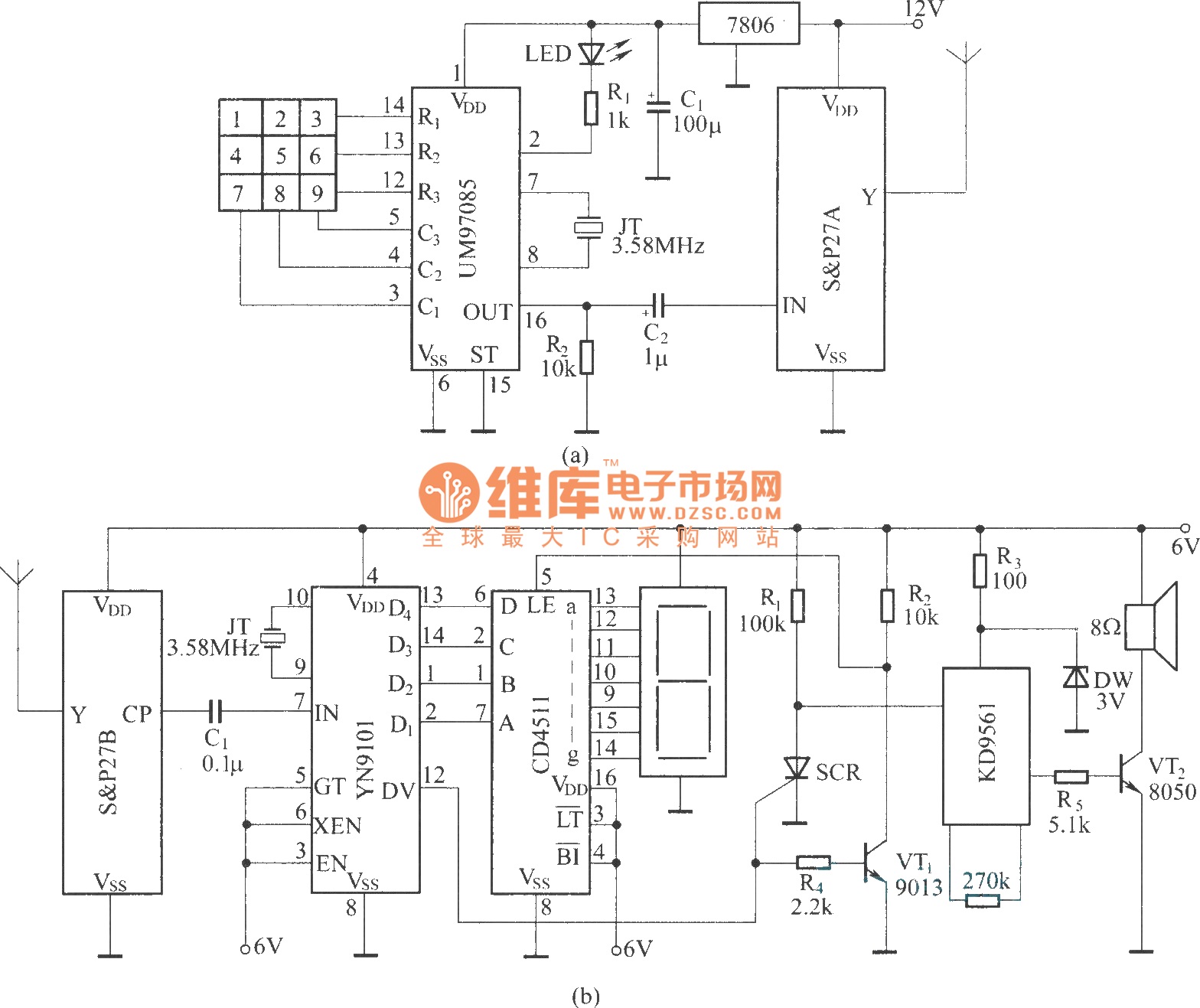
It utilizes a DTMF encoder output, which generates a dual-tone multi-frequency coded signal to modulate the transmitted carrier frequency. This configuration allows for the formation of a DTMF-encoded radio paging system. The circuit incorporates a DTMF encoding chip, UM97085,...