
Transparent Mode XBee Projects for Model Railroading

The setup involves critical considerations for ensuring effective communication between the Lenz LI100F interface and the XBee Explorer Serial. The Lenz LI100F acts as a bridge between the digital control system of the train layout and the wireless communication capabilities of the XBee module. The choice of 9600 bps as the operating speed is standard for many applications and provides a reliable data transfer rate for typical commands and responses in model train operations.
Utilizing a Null modem is essential in this configuration as it effectively swaps the transmit and receive lines, facilitating proper communication between two devices that are both configured as DCE. The physical connection is made using a suitable cable or a gender changer, ensuring that the pinouts align correctly for data transmission.
The versatility of the XBee modules is highlighted by their ability to operate at multiple baud rates, making them adaptable to various systems. This feature is particularly beneficial when integrating with older or different serial devices, ensuring that the communication speed can be matched to the requirements of the connected equipment.
In summary, this configuration serves as a robust solution for integrating a model train layout's control interface with wireless communication technology, enhancing the operational capabilities of the system. Proper attention to the connection methodology and configuration settings is crucial for achieving seamless communication between devices.The remaining equipment is installed at the train layout`s computer interface. The interface I used here is a Lenz LI100F configured to communicate at 9600bps. Both the LI100F and the XBee Explorer serial are configured as DCE (Data Communications Equipment) devices. These devices are intended to be connected directly to an RS232 serial port on a computer, and not to another DCE device. In order to connect the two devices, we were required to reverse the transmit and receive pins through the cable going between them. This is accomplished using a Null modem, which allows two DCE devices (or two DTE (Data Terminal Equipment (e.
g. computers) to communicate with each other directly. Additionally, both the LI100F and the XBee Explorer Serial have 9 pin female D-SUB connectors. We need to use a cable with two male ends to connect the two devices. Alternately, a male to male gender changer can be used. The The XBee modules can be configured to communicate through it`s serial port at 1200, 2400, 4800, 9600, 19200, 37400, 57600, and 115200 bps. This should allow matching it`s speed to most serial interfaces. 🔗 External reference
Related Circuits
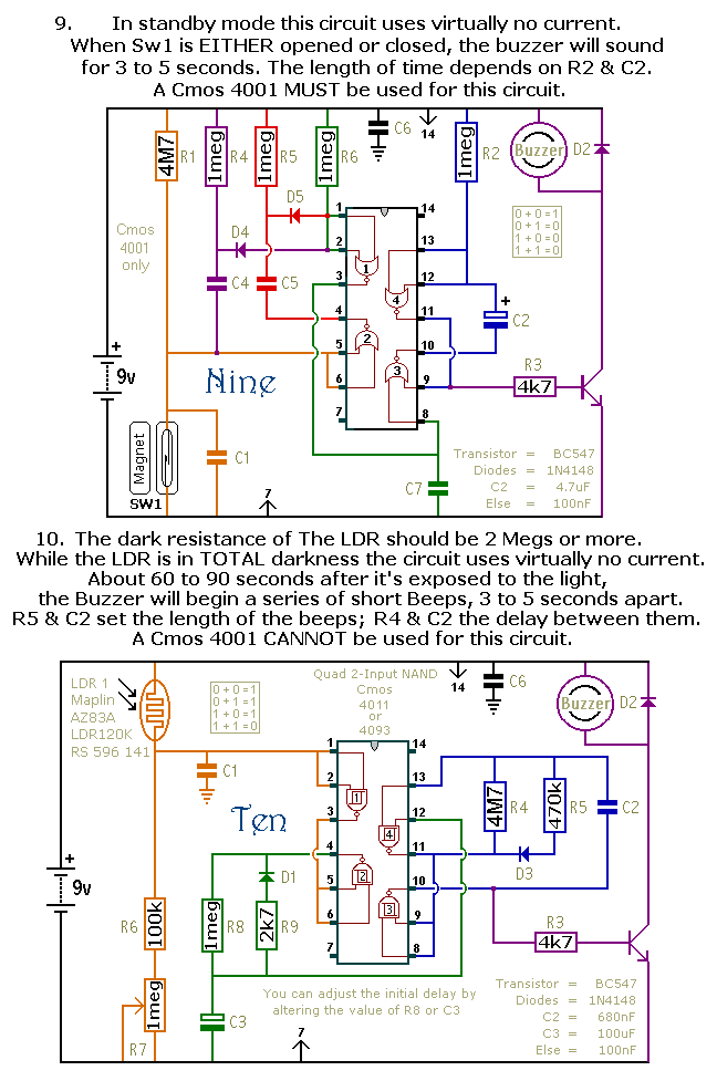
This document outlines a selection of small self-contained alarm circuits. Each alarm's main features are detailed on the circuit diagram. They are designed to have a very low standby current, making them suitable for battery operation. Each pair of...
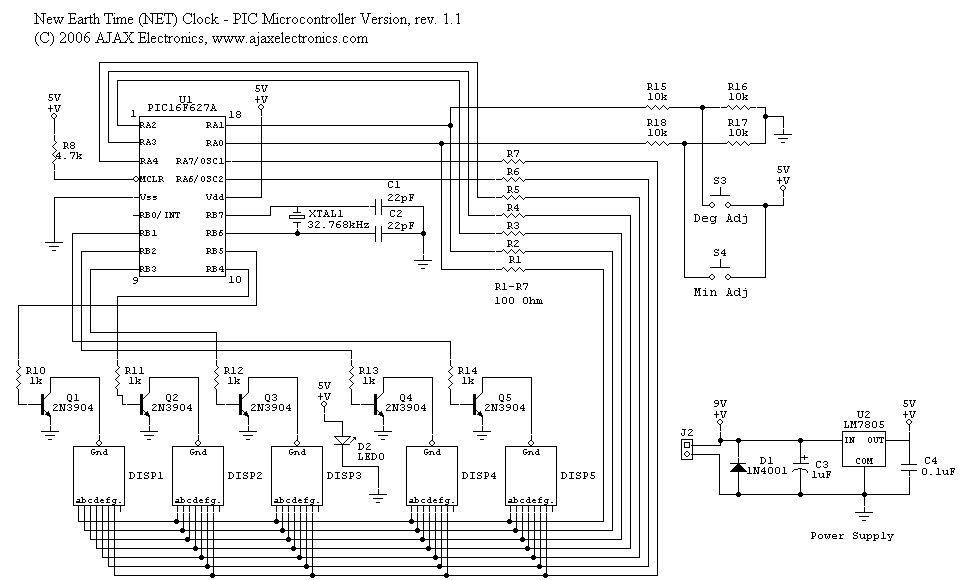
The schematic diagram and electronic assembly are relatively simple, as most of the functionality is managed by the microcontroller code. The schematic diagram serves as a visual representation of the electronic circuit, outlining the connections between various components such as...
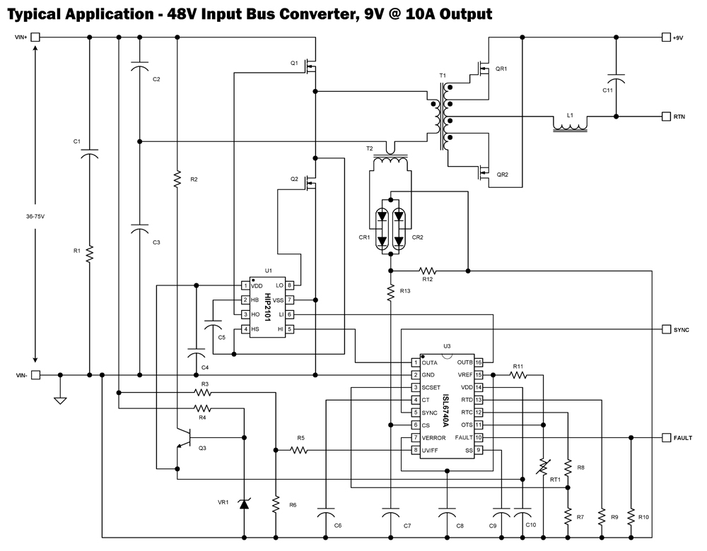
The ISL6740A is an enhanced PWM controller that incorporates built-in voltage feed forward functionality. It is pin and feature compatible with the ISL6740 double-ended pulse width modulation (PWM) voltage-mode controller, facilitating straightforward drop-in replacement in existing designs. Voltage feed...
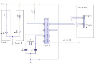
The dual-channel thermometer is a simple project based on a PIC microcontroller with ADC capabilities. It is an inexpensive thermometer that utilizes low-cost components and does not require high-sensitivity or expensive sensors. Instead, it employs a simple silicon diode...
This RS-232 to RS-485 protocol converter utilizes two components to form a complete operational system. The circuit adheres to all EIA and ITU specifications for RS-232 to RS-485 RS422 conversion. It features a robust design capable of handling ±15kV...
If you are interested in model aeroplanes and have the capital, a radio controlled electric park flyer is a must have. An RC aeroplane under 400 grams floats around like the rubber models of my youth and contact with...