
Model Aeroplane Navigation Strobe

The circuit described operates using a 555 timer integrated circuit, which is a versatile component commonly used in timing applications and pulse generation. The configuration allows for variable duty cycles, facilitated by the combination of the zener diode (D1) and the trim potentiometer (VR1). These components work together to stabilize the voltage supply to the timer, ensuring consistent operation regardless of the number of cells in the power supply, which can range from 6 to 8 cells.
The transistor (Q1) is employed as a current limiting device, ensuring that the output current to the connected load (in this case, a lamp) does not exceed 50 mA. This is crucial for preventing damage to both the lamp and the circuit components. The resistor (R1) serves to further stabilize the voltage across the zener diode, contributing to the overall reliability of the power supply.
Capacitor C1, specified as a tantalum capacitor, is likely used to filter and smooth the power supply, providing a stable voltage to the timer circuit. This is particularly important in applications where sudden changes in load current could otherwise disrupt the operation of the timer.
In summary, the circuit is designed to control a lamp using a 555 timer, with adjustable duty cycles and stable voltage regulation, making it suitable for various applications, including those in model aeroplanes, where weight and power efficiency are critical.If you are interested in model aeroplanes and have the capital, a radio controlled electric park flyer is a must have. An RC aeroplane under 400 grams floats around like the rubber models of my youth and contact with the ground doesn`t seems to involve that sickening crunch that comes with larger models.
Finding a deserted park in which to fly one (that propellor can still be dangerous) and waiting for a windless day isn`t always that easy but it sure beats driving an hour to a club field. Park flyers are definitely stress beaters and are also just plain fun This circuit should work with 6, 7 or 8 cells as zener D1 and trim pot VR1 make the duty cycle of the 555 timer chip adaptable and the transistor Q1 limits the lamp current to 50mA. R1 and D1 provide a near stable voltage so that C1 (I used tantalum 35w 🔗 External reference
Related Circuits

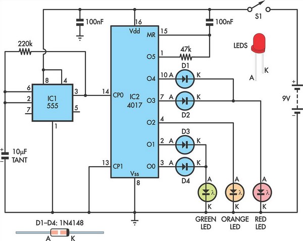
This circuit operates six LEDs in a "Knightrider scanner mode." The power consumption is primarily influenced by the type of LEDs utilized, especially when employing a 7555 (CMOS version of the 555 timer). Caution is advised when working with...
Children today appear to possess nearly all the items available in toy stores. Therefore, if there is a son or grandson with a collection of toy cars, here is a suggestion for an addition to that collection. For enhancing a...
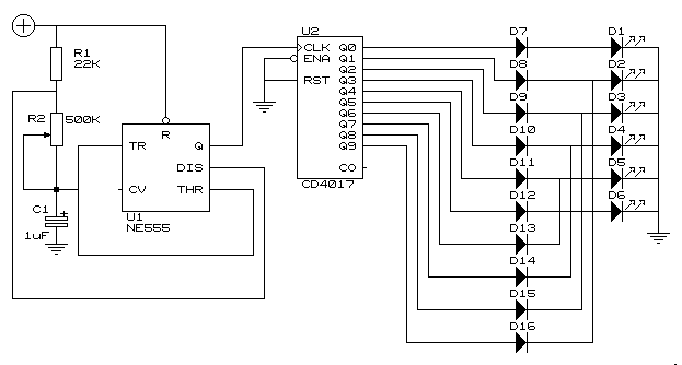
This simple circuit drives 6 LEDs in Knightrider scanner mode. Power consumption depends mainly on the type of LEDs used if you use a 7555 (555 CMOS version). More: Note that VDD and GND for the ICs are not...
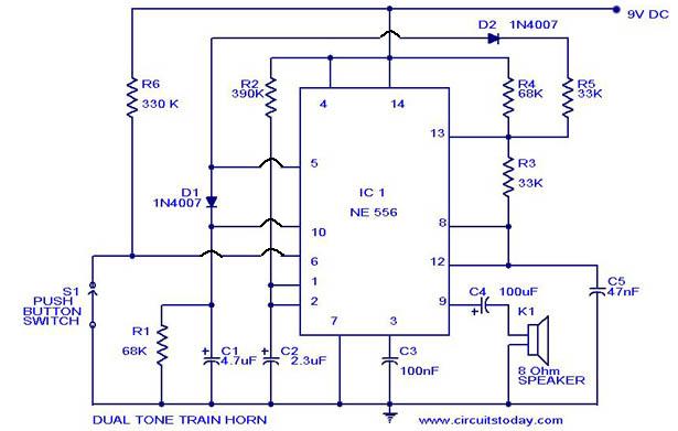
A dual-tone model train horn/sound generator/simulator circuit can be created using two NE 555 timers connected in cascade. However, the circuit diagram presented is designed with the NE 556 integrated circuit, which essentially comprises two 555 timers in a...
To capture high-speed photographs, a fast shutter or light source is essential. This project involved examining a commercial flash unit to analyze its light profile. A phototransistor was connected in an emitter follower configuration with a low impedance emitter...
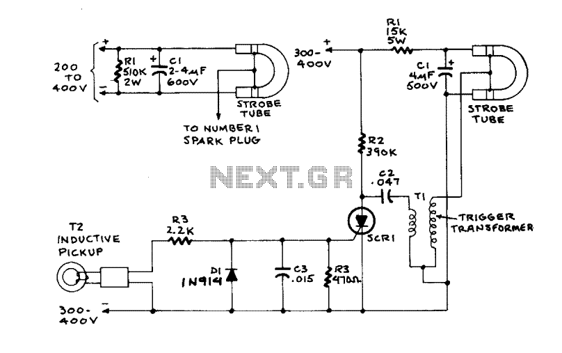
Figure A illustrates the circuit of a direct-trigger timing light. The trigger voltage is obtained from the vehicle's ignition circuit via a direct connection to a spark plug. Figure B depicts a circuit utilizing an inductive pickup. A trigger...