
Trf Radio

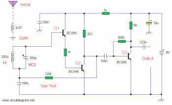
The AM radio circuit primarily consists of the Ferranti ZN414 IC, which is designed for low-power AM radio applications. The IC integrates most of the necessary functions for AM reception, including RF amplification, demodulation, and audio amplification, making it an ideal choice for compact radio designs.
The power supply for the circuit is a standard 9-V battery, which provides the necessary voltage for the operation of the ZN414 IC. This voltage level is suitable for the IC's specifications, ensuring efficient performance and minimal power consumption.
The antenna system is critical for the radio's reception capabilities. The 5-inch diameter ferrite rod serves to enhance the radio's sensitivity and selectivity. Ferrite rods are commonly used in AM radios due to their excellent magnetic properties, which improve the coupling of the radio waves to the coil. The antenna is constructed by winding approximately 85 turns of #28 enamelled wire around the ferrite rod. The choice of wire gauge and the number of turns are significant, as they determine the inductance and thus the resonant frequency of the antenna, optimizing it for AM band frequencies.
In addition to the antenna, the circuit may include components such as variable capacitors for tuning, resistors for biasing and feedback, and capacitors for filtering and coupling audio signals. These components work together to create a functional AM radio receiver capable of picking up local AM broadcasts with clarity.
Overall, this simple AM radio design exemplifies the effective use of a compact integrated circuit and a well-designed antenna system, making it suitable for hobbyists and educational purposes in electronics. This simple AM radio uses a Ferranti ZN414 IC and runs from a 9-V supply. A 5he"-diameter ferrite rod serves as an antenna, and u ses about 85 turns of #28 enamelled wire.
Related Circuits
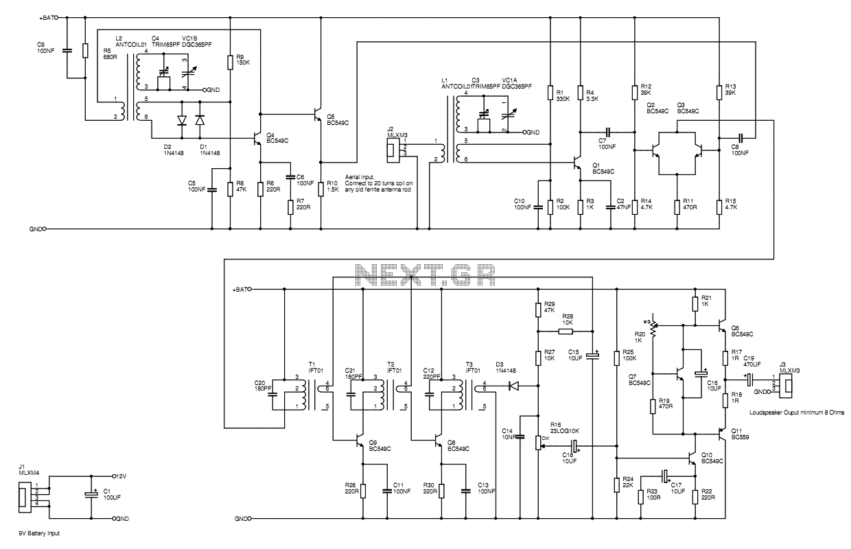
A MW AM radio like those you buy, or used to buy. Use just BC549 trannies, with the BC559 complement being allowed in the audio output stage. Buying RF antenna coils, oscillator coils and intermediate frequency transformers would be...
The AM radio receiver circuit diagram is based on the single integrated circuit MK484. The components list includes: R9, R10 (6.8 ohms), R6 (100 ohms), R3 (1k ohms), R1 (4.7k ohms), R7 (5.6k ohms), R4 (10k ohms), R2 (100k...
Function: step down the antenna impedance from high to 50 ohms and not, as would be expected, to effect a change from balanced to unbalanced. Component: .. In the context of antenna systems, impedance matching is crucial for maximizing power...
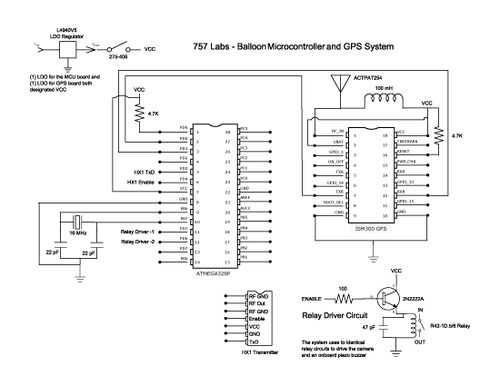
The balloon reached a peak altitude of 103,258 feet. Several factors needed to be considered when launching a payload to this height. Unlike creating an electronics package for sea level, variables such as air pressure, temperature, relative humidity, and...
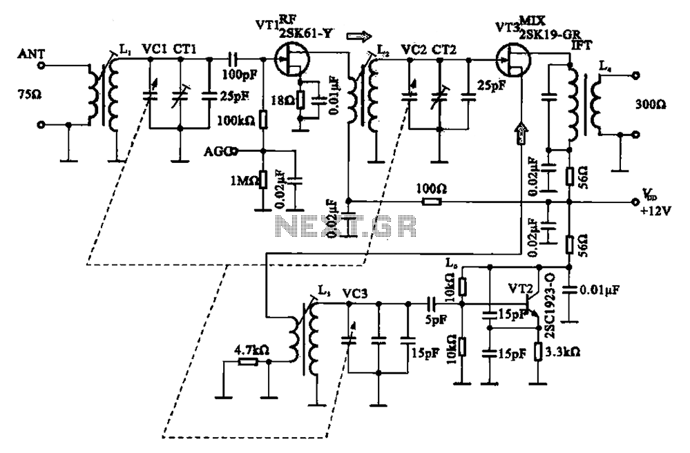
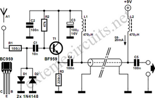
The FM radio circuit consists of a high-frequency amplifier (VT1), a mixer and local oscillator (VT2), and additional components. The circuit includes an FM radio antenna for signal detection, with an input transformer (L1) connected to a gate transistor...
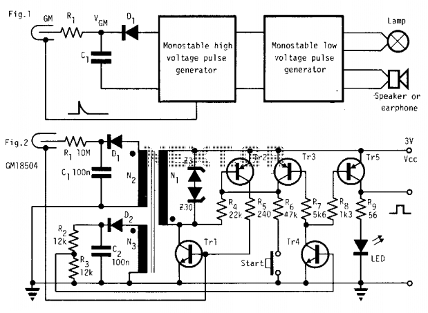
In the absence of radiation, no current is drawn. At normal background radiation levels, the power consumption is extremely low. The instrument may be left on for several months without changing batteries. In this way, the detector is always...