
Tri-Tet Oscillator

The Lamb tri-tet oscillator is diagrammed for transmitting use in the June 1933 QST magazine article that introduced it. The circuit has been updated to resistively load the crystal less and to facilitate cathode-only keying by breaking the DC connection between the cathode tuned circuit and common, with its grid-leak resistor decoupled by an RF choke and returned to common instead of the tube cathode. The cathode tuned circuit, consisting of L1 and C1, is relatively high-capacitance and tuned to a frequency between the crystal's fundamental and second harmonic—typically 5.9 MHz (3.3 H in parallel with 220 pF) for a 3.5-MHz crystal. The output tuned circuit resonates at or near a crystal harmonic or, if a well-screened tube is used, near the crystal fundamental. It is crucial that the cathode tuned circuit is not tuned near the crystal fundamental to avoid damaging the crystal; therefore, C1 should not be variable in any modern practical application of the tri-tet.
The genesis of the tri-tet as an electron-coupled crystal oscillator is rooted in earlier works on electron-coupled oscillator circuits. Jim Lamb's introduction of the tri-tet circuit in June 1933 QST and insights from prior articles highlight the evolution of this technology. The tri-tet concept was foreshadowed in an early Hints and Kinks item, which accurately described using a tuned-near-the-crystal-frequency tank circuit in the screen of a power pentode or dual-grid power tube, along with a second tank in the plate circuit tuned to a harmonic.
The tri-tet's underlying innovation lies in the realization that the screen of a tetrode or pentode tube operates at a positive voltage relative to the control grid and is electronically downstream from it. This allows the screen, often referred to as the accelerator grid in audio power tubes, to function as an oscillator anode. Consequently, the plate of such a tube can be utilized to couple output from the cathode-grid-screen-triode oscillator through the tube's cathode-to-plate electron flow. This configuration enables effective RF generation and amplifies the capabilities of single-tube crystal transmitters, making the tri-tet oscillator a significant advancement in amateur radio technology.QST`s most recent development ”the Tri-tet oscillator ”has made the single-tube crystal transmitter a really practical affair at last. Practical because it is now possible to work equally well in two ”and, in a pinch, in three ”amateur bands with a single crystal.
Unless we miss our bet, this particular set marks the beginning of the era in wh ich the new amateur`s first transmitter will be crystal controlled. ”from the deck of George Grammer, "A One-Tube Crystal-Controlled Transmitter, QST, March 1934, pages 8 12, 88 The tri-tet (triode-tetrode, also commonly spelled tritet) oscillator circuit (Figure 1) was announced in James Lamb, W1CEI, "A More Stable Crystal Oscillator of High Harmonic Output, " QST, June 1933, pages 30 32, as an improved means of generating radiofrequency (RF) power at harmonics (multiples) of the frequency of an oscillating piezoelectric frequency-control crystal. Misunderstood and misused, it went on to be reviled as a temperamental crystal destroyer. This page discusses the tri-tet`s genesis, characteristics, and adjustment, and shows how the tri-tet, properly used, is nonetheless an excellent means of achieving good keying and high power output in a one-stage radio transmitter.
Figure 1 ”(A) The Lamb tri-tet oscillator as diagrammed for transmitting use in the June 1933 QST magazine article that introduced it. (B) The Lamb tri-tet redrawn with its screen-grid tube portrayed a bit more modernly, and ”to resistively load the crystal less, and to allow cathode-only keying (as opposed to B keying) by breaking the dc connection between the cathode tuned circuit and common ”with its grid-leak resistor decoupled by an RF choke and returned to common rather than to the tube cathode.
The cathode tuned circuit, L1C1, is relatively high-C and is tuned to a frequency between the crystal fundamental and second harmonic ”typically 5. 9 MHz (3. 3 H in parallel with 220 pF) for a 3. 5-MHz crystal. The output tuned circuit resonates at or near a crystal harmonic or ”if a well-screened tube is used ”near the crystal fundamental.
The cathode tuned circuit, L1C1, must not be tuned near the crystal fundamental or destruction of the crystal may result; for this reason, C1 should not be variable in any modern, practical application of the tri-tet. The tri-tet`s genesis as an electron-coupled crystal oscillator: Electron-coupled oscillator basics and value (J.
B. Dow, "Electron-Coupled Oscillator Circuits, " QST, January 1932, pages 23 25; George Grammer, W1DF, "Electronic-Coupled Oscillators for the Small Transmitter, " QST, October 1932, pages 13 17, 88. Jim Lamb`s introduction of the tri-tet circuit in June 1933 QST ("A More Stable Crystal Oscillator with High Harmonic Output, " pages 30 32) ”but also a snippet from an early Hints and Kinks item (William P.
Durkin, W2DHM, "Combined Oscillator and Doubler, " For the Experimenter, QST, December 1932, pages 40 41) that (a) prefigured the tri-tet idea accurately by using a tuned-near-the-crystal-frequency tank circuit in the screen of a 47 power pentode or the second grid of a 46 dual-grid power tube with a second tank in the plate circuit tuned to a harmonic, and (b) Lamb did not explicitly credit in his introductory (and any later) article. Multiple forms of the tri-tet: The underlying genius of the electron-coupled oscillator was the discovery that because the screen of a tetrode or pentode tube operates at a positive voltage relative to the tube`s control grid and is electronically downstream from the control grid, the screen (more accurately called the accelerator grid in an audio power pentode or audio beam-power tube because its intended function is electron acceleration rather than electrostatic grid-plate shielding) can serve as an oscillator anode.
This allows the plate of such a tube to be used to couple output from the cathode-grid-screen-triode oscillator through the tube`s cathode-to-plate electron 🔗 External reference
Related Circuits
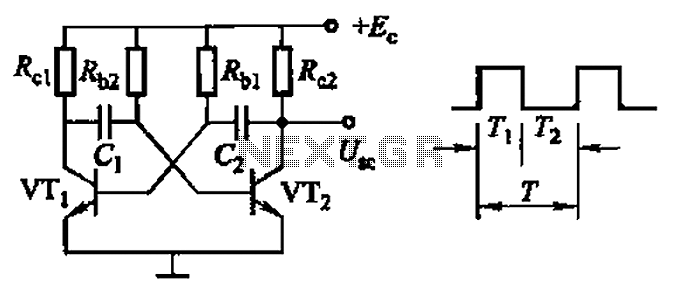
Common non-sinusoidal oscillator circuit, waveform and frequency formula - square wave oscillator - self-excited multivibrator The common non-sinusoidal oscillator circuit, specifically the square wave oscillator, is a fundamental electronic circuit utilized to generate square wave signals. It operates based on...
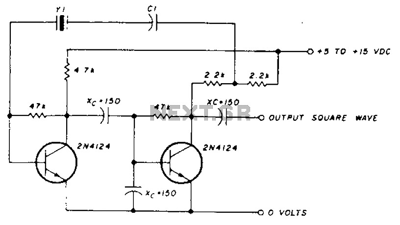
A transistor in series with capacitor C1 can be utilized to adjust the oscillator output frequency. The frequency may vary with changes in capacitance ranging from 20 pF to 0.01 µF, or as determined by the tuning capacitor. The...
This is an astable multivibrator (oscillator) circuit using a CMOS inverter. The circuit employs the CD4007 or MC14007 integrated circuit. The operating frequency range of this circuit is not specified. The astable multivibrator circuit utilizes CMOS technology to create a...
An attempt has been made to follow an instructable for some time; however, understanding its schematic remains challenging. The issue is not a lack of knowledge regarding the symbols used. In electronic schematics, symbols represent various components and their connections...
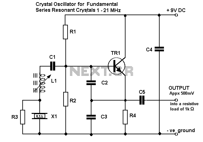
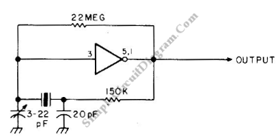
On following pages circuits are shown for 3rd overtone crystals 15 to 65MHz and 5th overtone crystals 60 to 105 MHz operating in their series resonant mode. In both of these circuits with the crystal short circuited, the oscillator...
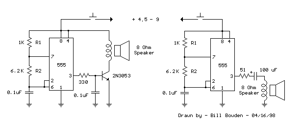
This is a basic 555 squarewave oscillator used to produce a 1 kHz tone from an 8-ohm speaker. In the circuit on the left, the speaker is isolated from the oscillator by the NPN medium power transistor, which also...