
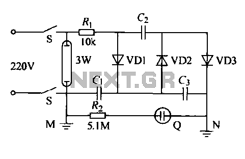
TRIAC LAMP DIMMER

The circuit utilizes a TRIAC (TR1) for controlling high power loads, with a maximum power handling capability of 350 watts when adequately cooled with a heatsink. The heatsink is essential for dissipating heat generated during operation, ensuring the TRIAC remains within safe temperature limits to prevent thermal failure.
The neon lamp (I1) serves as an indicator and a triggering mechanism for the TRIAC. It remains non-conductive until a specific voltage threshold is reached. Once this threshold is surpassed, the neon lamp will conduct, providing a triggering voltage to the gate of the TRIAC. This mechanism allows for precise control over the TRIAC's operation, ensuring it only activates when the desired conditions are met.
Resistor R1 plays a critical role in setting the desired lighting level. By adjusting the resistance value, one can control the amount of current flowing through the circuit, thereby influencing the brightness of the connected load. This feature provides flexibility in lighting applications, allowing users to customize the intensity according to their needs.
The overall design is suitable for various applications, including lighting control systems, where dimming capabilities are essential. Proper attention must be given to the selection of the heatsink, TRIAC, and resistor values to ensure optimal performance and reliability of the circuit.Using a heatsink, the TRIAC (TR1) can handle up to 350 watts. The neon lamp, I1, won`t trip the gate until after it conducts and using R1, set the lighting wherever you want it. 🔗 External reference
Related Circuits
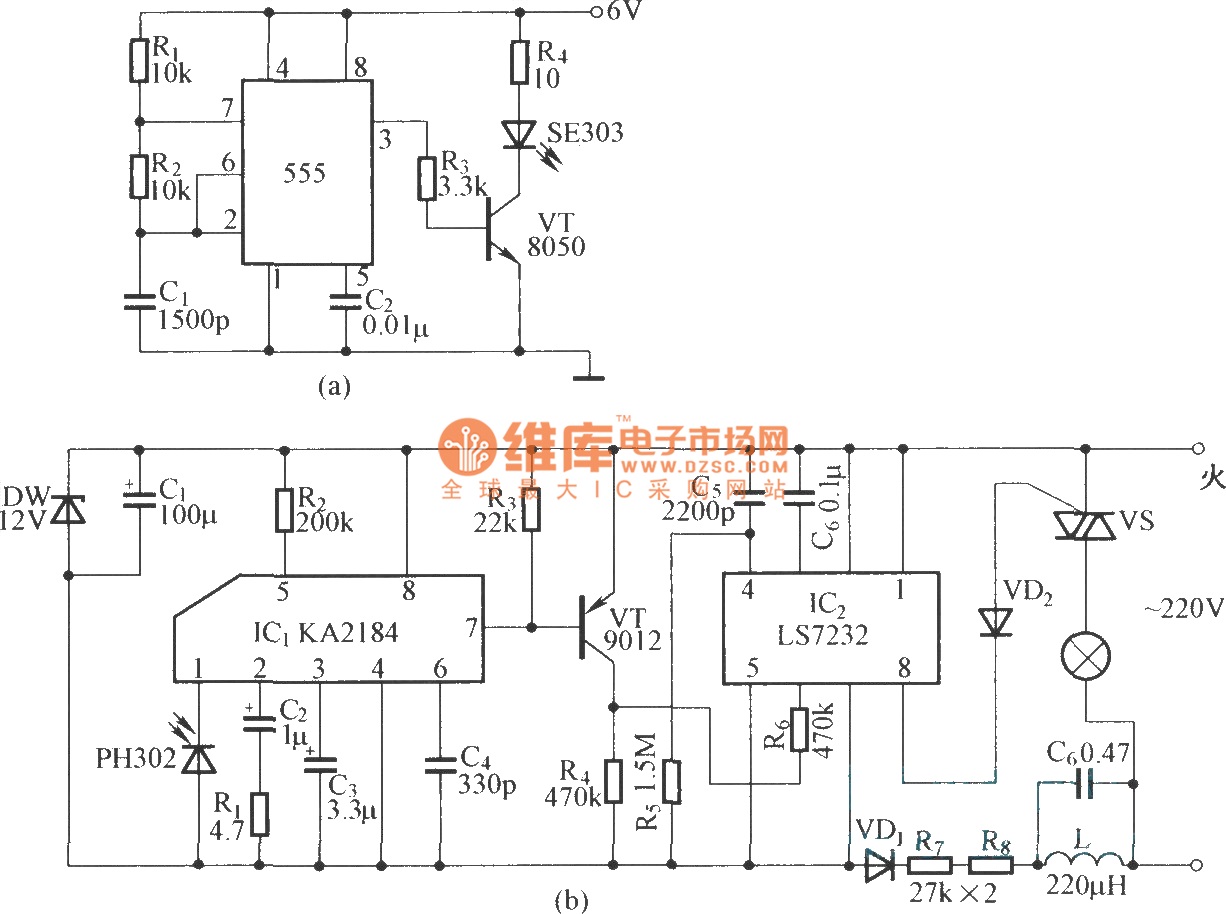
This is an infrared emission circuit diagram. The NE555 circuit generates a 40 kHz pulse, which is sent by the infrared emission control SE303 after being amplified by VT. The remote receiver and infrared dimming circuit are composed of...
The IED functions as a hotel, restaurant, and family-oriented tool designed for the effective eradication of mosquitoes, as illustrated in Figure 16-12a. It employs a diode voltage doubler rectifier circuit to generate a high voltage. When mosquitoes are attracted...

A simple touch dimmer circuit diagram using the TT6061 IC, which is a touch control integrated circuit used for light dimmer circuits and lamp dimmer circuits. The touch dimmer circuit utilizing the TT6061 IC is designed to provide a user-friendly...
Switching to alternative power sources can help reduce electricity bills. The photovoltaic module or solar panel described here is capable of generating renewable energy. The photovoltaic module, commonly known as a solar panel, is a device that converts sunlight into...
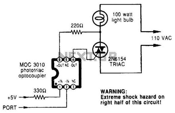
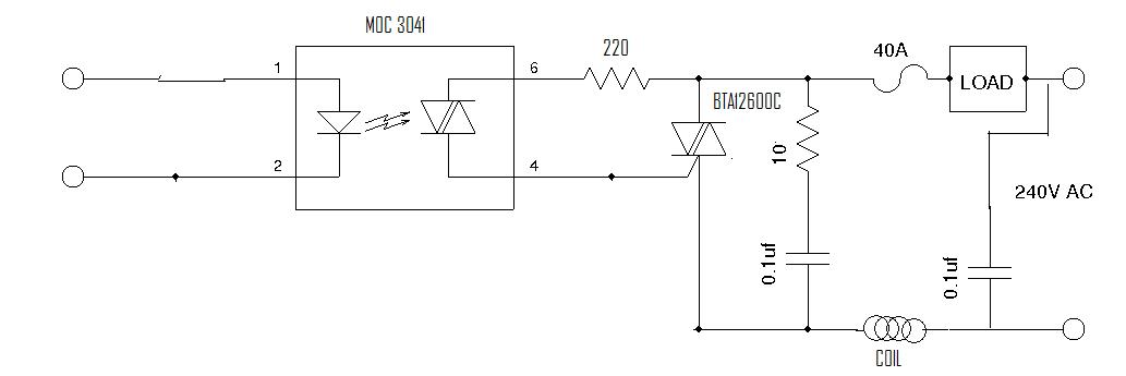
A microcomputer-to-triac interface utilizes a phototriac optoisolator to safely isolate logic signals, allowing direct control of high-power loads. This circuit can function as either an on/off switch or a proportional phase control, depending on the input waveforms and the...
Even though the power was off, there was AC present at the handle plug, and a short circuit occurred. Upon disassembly, a blown transistor was discovered. An attempt was made to fix the issue, but after one month and...