
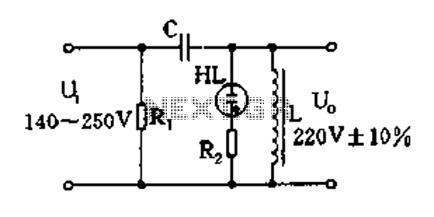
Triac regulation of mains voltage

Triac regulation circuits are essential for controlling the power delivered to various electrical devices, allowing for a versatile range of applications in home and industrial settings. The triac functions as a semiconductor switch, enabling precise control over the power output by adjusting the phase angle of the AC waveform. This method of control is particularly effective for resistive loads like incandescent bulbs and heating elements, where the power can be smoothly varied without introducing significant harmonic distortion.
The use of the integrated circuit U2008B enhances the reliability and performance of the circuit, providing a robust control mechanism for the triac. The circuit design must consider the thermal management of the triac, as excessive heat can lead to failure. Therefore, adequate heatsinking is necessary for high-power applications, ensuring that the triac operates within its specified temperature range.
The circuit's safety features are paramount, given the high voltages involved. The recommendation to use a potentiometer with a plastic shaft minimizes the risk of electric shock, while the note regarding the non-isolated metal case of the triac serves as a crucial reminder for proper handling and installation practices. All components should be rated for the expected electrical loads and voltages to maintain circuit integrity and safety.
In summary, the triac regulation circuit provides a practical solution for controlling the power of various electrical appliances, combining effective performance with necessary safety considerations. Proper component selection, circuit design, and adherence to safety protocols are essential for successful implementation in real-world applications.Triac regulation suited to regulate the power of mains appliances. It can regulate the brightness of incadescent light bulbs, halogen, dimmable energy savers, the power of heaters and other thermal appliances, engine (motor) regulation, etc. Fits as well to regulate certain types of Tesla transformer (eg SSTC). Power can be easily ad justed from 0 to 100% by simply turning the potentiometer. Triac regulation uses the triac as a switching element. Triac is triggered at some phase by pulse to the control electrode G (Gate) and remains conductive until the line passes zero voltage. There are also some regulators made of discrete components, but as the most reliable I found the involvement of an integrated circuit U2008B.
The schematic diagram below shows triac regulation circuit for 220V / 230V / 240V mains voltages. Power is adjusted by P1. If the regulations does not regulate in full range, adjust R1 or R2. The triac operates in quadrants II and III. Caution - note that the electrolytes in the diagram have positive pole at neutral. The resistors with no wattage noted are miniature. Triac Tc1 has to be sufficiently dimensioned according to the load. For higher powers, place it on the heatsink. You can use for example BT134, BT136 to 4A, BTB12 to 12A, BTA16 to 16A or BTB24 to 24A. Triac must also be rated to sufficient voltage, I recommend at least 600V. Warning: The whole circuit is at mains voltage! To ensure safety, it is necessary to use suitable potentiometer (with plastic shaft). Metal case of triac is not isolated from the mains! Connected appliance should always be treated as live, even if the regulation is set to zero power. The appliance is still under voltage! 🔗 External reference
Related Circuits
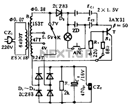
This circuit is designed for high current applications using nickel-cadmium rechargeable batteries, and it can also function as a general low-voltage DC power supply. The circuit consists of a charging section and a DC output section. K2 serves as...
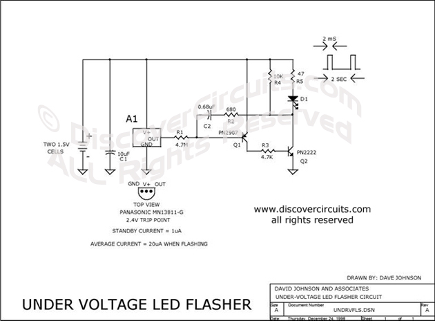
Many battery-powered devices utilize two AA alkaline cells. Often, the user is unaware of when to replace the batteries until the device ceases to operate. The hobby circuit described below can be connected to a 3V battery, providing a...
Easy exchange of magnetic saturation voltage regulator circuit The magnetic saturation voltage regulator circuit is designed to stabilize output voltage levels by utilizing magnetic saturation principles. This circuit typically employs a magnetic core, which operates in saturation to regulate...
An alternative approach to utilizing operational amplifiers (op-amps) for power supply regulation is presented. This method necessitates an additional winding on the power transformer to provide the op-amps with a bipolar voltage of +/- 8 volts. The negative voltage...
Neither term describes a regulator, only its placement within a circuit or system. Any voltage regulator could meet the requirements, depending on its placement. A listing of Analog Voltage Regulator IC manufacturers. The types of products or devices they...

Consider a capacitor with capacitance C that charges to a voltage V and discharges to 0V at a frequency of 5 times per second. To estimate the average current, also referred to as the RMS current, a rough approximation...