
Triac zero voltage switching

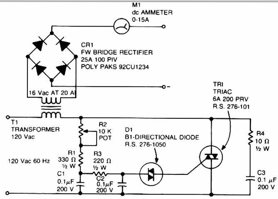
The circuit utilizes a triac for controlling power in AC applications, specifically designed to handle alternating current by switching on and off in response to the AC waveform. The operation begins with the positive half cycle of the AC signal, where the 3 µF capacitor plays a crucial role in delivering the necessary gate current to the triac. This gating action occurs only when the C103 SCR is not conducting, ensuring that the triac remains off until the appropriate conditions are met.
As the load voltage rises during this phase, it charges the 1 µF capacitor. This capacitor serves as a timing element that enables the triac to be triggered again during the next negative half cycle. The timing and control of this operation are vital for applications requiring precise power management, such as in lighting control or motor speed regulation.
The selection of a specific gate triac is important due to the III+ triggering mode, which is a method of controlling the turn-on point of the triac in relation to the AC waveform. This mode allows for finer control over the phase angle at which the triac is triggered, thus enabling efficient power delivery and reduced electrical noise.
In summary, the described circuit effectively utilizes capacitive coupling and controlled triggering to manage AC loads, ensuring that the triac operates efficiently across both halves of the AC cycle while accommodating the requirements of the III+ triggering mode.The triac will be gated on at the start of the positive half cycle by current flow through the 3 µf capacitor as long as the C103 SCR is off. The load voltage then charges up the 1 µF capacitor so that the triac will again be energized during the subsequent negative half cycle of line voltage
A selected gate triac is required because of the III+ triggering mode.
Related Circuits
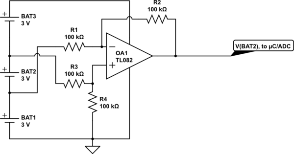
Utilize a high-performance microcontroller (Piccolo TMS320F28035, 12-bit resolution, +/- 4 LSB offset, +/- 60 LSB gain) to measure the voltage across stacked battery cells and control related analog electronics for charge equalization. The microcontroller will also save data in...
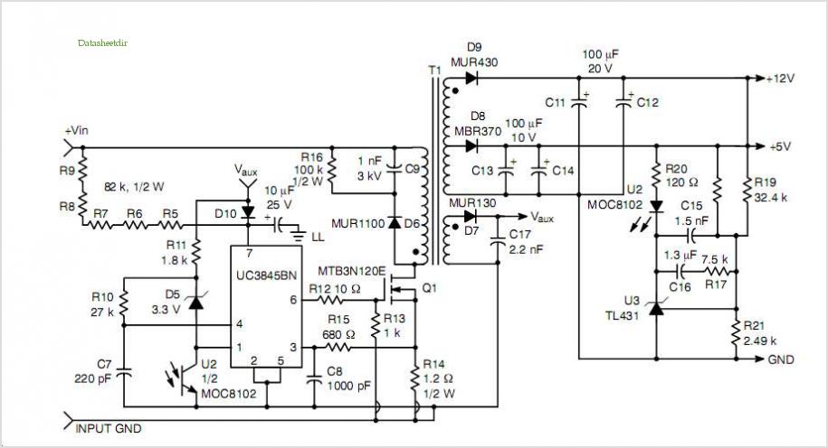
This post summarizes the work of experts in switching power supply schematic diagrams who are thoroughly knowledgeable about all aspects of the subject. Switching power supplies are crucial components in modern electronic devices, providing efficient voltage regulation and power conversion....
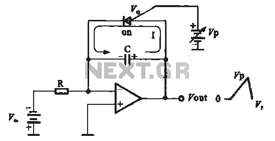
A sawtooth voltage-controlled oscillator operates by first generating a negative potential maximum at the output of the comparator. This output is then fed to the inverting input terminal through resistor R1, which is part of the relaxation oscillator. The...
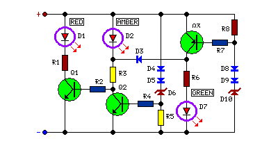
This circuit monitors battery voltage and features a three-LED display. By connecting this circuit to the battery of a vehicle, users can easily determine the approximate voltage at a glance. The battery voltage monitoring circuit utilizes a simple yet effective...
This circuit can be used to charge accumulator and cell batteries. It features a very stable output that extends the battery life and maximizes the added battery capacity. The charging process is also quite fast, optimizing the time required...
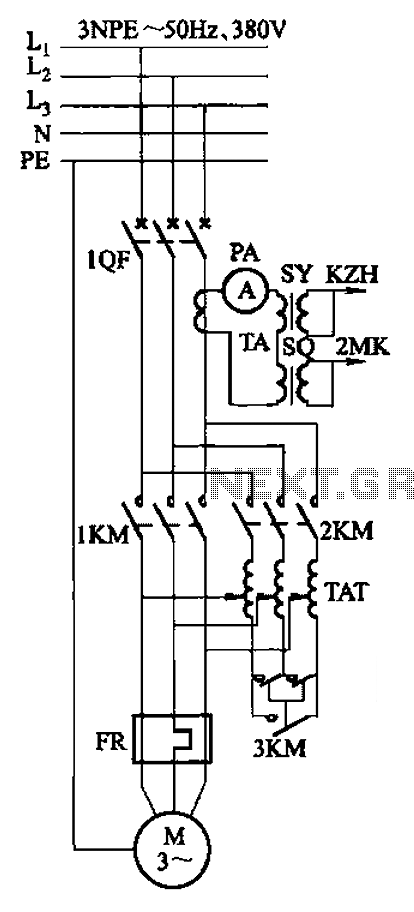
Autotransformer voltage starting, with an adjustable starting time of 30-60 seconds. It includes the SDJ electrode liquid level sensor of HJ-13 type, a pump control system box of HKD-21B type, 1MK level modules adopted by HKG-1SG type, 2MK start...