
Triangle wave generator circuit with cmos inverter IC

The function generator circuit utilizes the CD40106, which is a Schmitt trigger inverter. This IC is well-suited for generating square waves due to its fast switching capabilities and hysteresis characteristics, which help to create clean, distinct transitions between high and low states. The circuit can be configured to produce a triangle wave by integrating the square wave output using an RC (resistor-capacitor) network.
In the typical configuration, the output of the CD40106 is connected to a resistor-capacitor network that shapes the square wave into a triangle wave. The resistor (R) and capacitor (C) values determine the frequency and amplitude of the generated waveforms. The square wave output can be taken directly from one of the inverter outputs, while the triangle wave can be obtained from the junction of the resistor and capacitor.
A standard transistor is often included in the circuit to amplify the output signal or to drive a load. This transistor can be configured in a common emitter or common collector arrangement, depending on the desired output characteristics. The choice of transistor will depend on the required output current and voltage levels.
Overall, this function generator project is versatile and can be used in various applications, such as signal processing, waveform generation for testing, and educational purposes in electronics. Adjustments to the resistor and capacitor values allow for a wide range of frequencies and waveform shapes, making it a valuable tool for experimentation and learning in the field of electronics.This is a very Function Generater project. can be used Triangle and Squarewave Generator. The main parts are CD40106 popular CMOS IC and a normal transistor is.. 🔗 External reference
Related Circuits
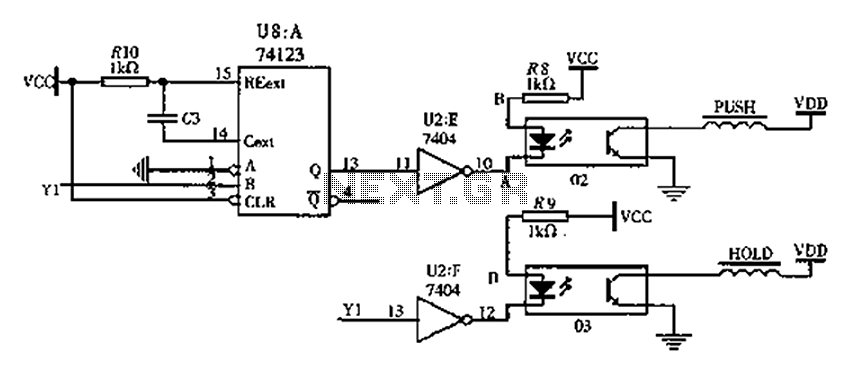
The FIG switching solenoid driver circuit utilizes the 74123 device chip (U8) and solid-state relays (02, 03). The switching electromagnet coil is referred to as the PUSH coil, while the HOL is maintained at a power supply voltage (VDD)...
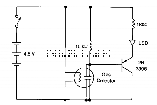
The circuit illustrates a basic yes/no gas detector. It utilizes three 1.5-V D cells as the power source, with SI functioning as an on/off switch. The heater is powered directly from the battery, while the electrodes are connected in...
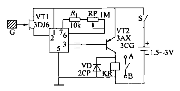
This circuit is a constant current protection type that limits the output current to a specific value in cases of over-current and short-circuit conditions. When the output current exceeds this limit, the output voltage decreases. The CW200 power management...

This page features a circuit that has twenty open collector outputs that turn on one at a time in a continuous sequential manner. The circuit utilizes the 74LSxx family of TTL integrated logic devices. The circuits are designed to...
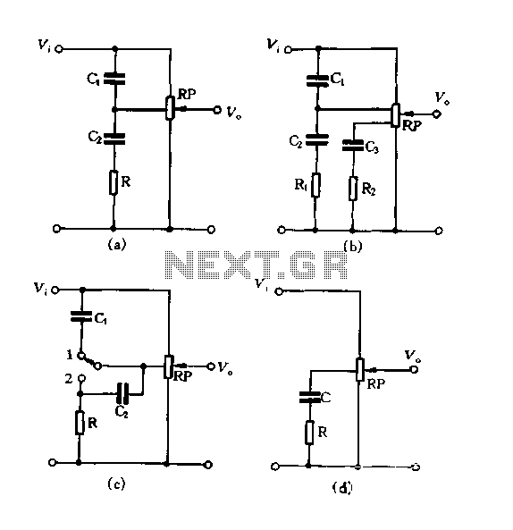
Figure 1.88 illustrates the loudness control circuit utilizing multiple taps on a potentiometer. In Figure (A), the connection is made between the tap and the potentiometer's input, along with the ground. An RC compensation network is employed, where the...
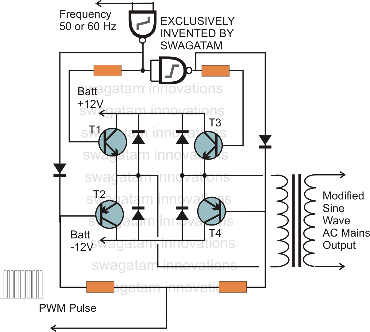
In electronics, an H-bridge circuit refers to a configuration consisting of four individual switching devices, such as transistors or MOSFETs, which can be controlled by external discrete signals from the respective stages of the control circuit. During operation, the...