
Triple Stroboscope Circuit

The described circuit is designed around the NE555 timer IC, which is widely used for generating precise timing pulses and oscillations. In this application, the NE555 is configured in astable mode, allowing it to produce a continuous square wave output. The frequency of the output signal can be modified by adjusting the resistance of potentiometer P1, which alters the charge and discharge times of the timing capacitor connected to the NE555.
The power supply for this circuit is derived from a transformer (TR1), which steps down the voltage from the mains supply. The AC voltage output from the transformer is then rectified using a traditional bridge rectifier configuration, converting it to a DC voltage. To ensure stable operation and to protect the circuit from voltage spikes, a Zener diode is incorporated into the power supply design. This diode regulates the voltage and provides a consistent operating voltage for the NE555 timer.
The ability to place the control potentiometer P1 up to 30 meters away from the circuit allows for flexibility in the setup of the stroboscope. This feature is particularly useful in applications where the stroboscope needs to be suspended or positioned at a distance for optimal observation of movement. The remote adjustment capability enhances user convenience and operational efficiency, enabling precise control over the stroboscopic effect without the need for direct access to the circuit.
Overall, this circuit is an effective solution for generating stroboscopic effects and observing movement, combining ease of use with reliable performance.This circuit enables observation of movement between other stroboscopes. Generation of rectangular signal is based on NE555. This circuit requires a low power supply that is made from a simple transformer TR1, traditional rectifier bridge and zener diode. The frequency is adjusted by potentiometer P1. The control potentiometer P1 can be placed as far as 30 meters away, for suspension of stroboscope ½s work from far away. 🔗 External reference
Related Circuits

Below are three examples of controlling a relay from the PC's parallel printer port (LPT1 or LPT2). Figure A shows a solid-state relay controlled by one of the parallel port data lines (D0-D7) using a 300-ohm resistor and a...

The Joule thief circuit is well-known among electronics enthusiasts. It has numerous implementations, but the most common is a very minimalist voltage booster. In the simulation file, a 1.5V battery is attached, which is the voltage of a new...

The required output from the inverter is 220/230V at 60Hz, with an output power of 1000VA. The first circuit represents a basic commercial UPS design, providing a constant regulated 5V output and an unregulated 12V supply. Upon failure of...
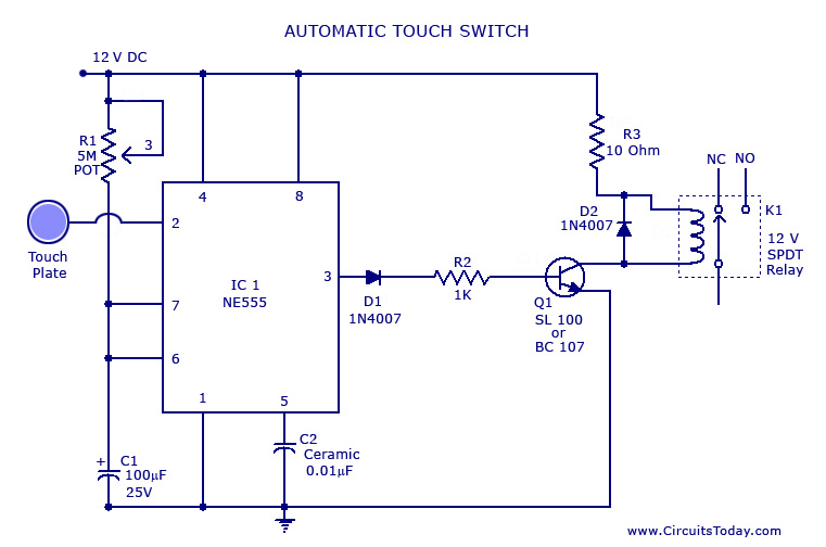
A touch switch circuit schematic utilizing a 555 integrated circuit (IC). When the touch plate is activated, a relay is switched ON for a predetermined duration, which can also be adjusted. The touch switch circuit employs a 555 timer IC...
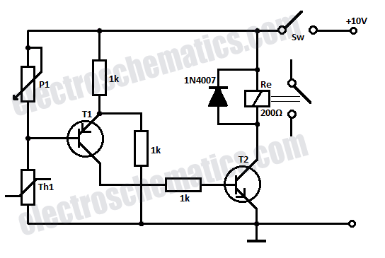
Safety is a significant concern in many motor-driven applications. This is particularly true in industrial settings where motion begins immediately upon the application of power. In motor-driven applications, safety mechanisms are essential to prevent accidents and ensure the well-being of...
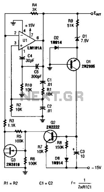
For variable-frequency operation, Rl and R2 can be replaced by a dual potentiometer. In electronic circuits that require variable-frequency operation, the use of a dual potentiometer as a replacement for resistors Rl and R2 can provide enhanced functionality and flexibility....