
Tritium Solar engine

The Tritium circuit, classified as a type 3 solar engine (SE), represents an early experimental design that serves as a prototype for further development. The circuit's primary component is an NPN transistor (Q1), which plays a crucial role in regulating the flow of current through its base-emitter junction. The operation begins with the solar energy being harnessed to charge a capacitor, which is integral to the circuit's function.
In this configuration, the capacitor charges through the base-emitter junction of Q1. During this phase, the transistor remains in a saturated state, allowing current to flow freely. This results in the collector voltage being held low, effectively maintaining a stable state until the capacitor reaches a certain charge threshold. As the charging current diminishes, the transistor transitions from saturation, causing the collector voltage to rise due to the lack of sufficient base current to keep it in the low state.
The design of the Tritium circuit emphasizes its experimental nature, as it has been observed to outperform other existing solar engine designs, such as the Freds. This performance can be attributed to the efficient charging mechanism facilitated by the NPN transistor, which allows for a rapid response to changes in solar input. The prototype nature of the circuit suggests that while it demonstrates promising results, further refinement and optimization are necessary to enhance its reliability and efficiency in various applications.
Overall, the Tritium circuit serves as a significant step in the evolution of solar engine technology, providing insights into the potential for improved designs and applications in renewable energy systems.The Tritium circuit was the first (to my knowledge) type 3 SE. As such, it is quite experimental, and should be regarded as a prototype rather than the `state of the art`! Nevertheless, it does function reasonably well, and in some circumstances outperforms other solar engines such as the Freds that I have lying around.
It works by charging the capacitor through the base-emitter junction of an NPN transistor (Q1). When current is flowing through this junction, the collector is held low. When the charging current tapers off, the collector will start to drift higher pulled 🔗 External reference
Related Circuits
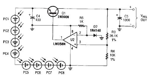
The circuit diagram illustrates a portable solar charger that utilizes an LM358N operational amplifier and a single transistor. This regulator delivers a constant output of 2.4 volts DC, suitable for powering small devices requiring energy from two AA battery...
A model has been constructed based on the principles of a horizontal steam engine, where the steam cylinder is substituted with an electromagnet featuring a moving core. The construction specifics are less significant, as the accompanying photos provide all...
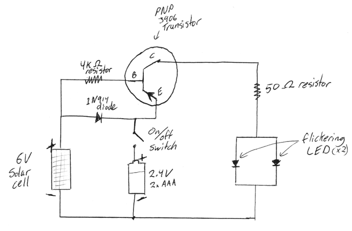
This is a DIY electronics project designed to enhance circuit design and building techniques. Copper lanterns were purchased and fitted with a circuit similar to outdoor solar lights. The circuit design is adapted from a simple design found on...
The controller for the Hybrid Power Plant (HPP) is represented in a block diagram format. It consists of 440 Wp photovoltaic modules, a 1 kW wind turbine, and a 5 kW diesel engine as a backup power source. The...
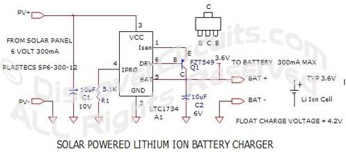
This is a simple NiCd battery charger powered by solar cells. A solar cell panel or an array of solar cells can charge a battery at more than 80% efficiency. The described circuit functions as a basic NiCd battery charger...
One 1381 part (CMOS voltage-controlled trigger available at different limits) should be selected to match the voltage across the motor (2V in this case). The other terminal of the motor is connected to a 3300µF capacitor, which is in...