
Solar Powered Lantern

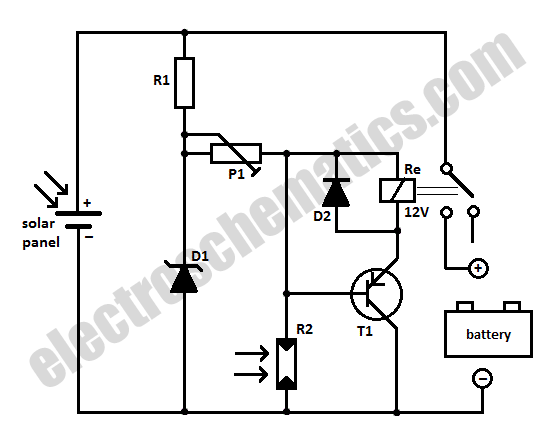
This project involves creating a solar-powered lighting system using copper lanterns, which are modified to incorporate a solar charging circuit. The circuit's foundation is derived from established designs, specifically tailored for indoor use, ensuring functionality even with limited light exposure. The choice of a 6V solar panel is critical, as it allows for effective battery charging through indirect sunlight, mitigating the need for direct exposure.
The components of the circuit include the 6V solar panel, a rechargeable 2.4V battery, and a light-emitting diode (LED) or similar light source. The solar panel captures ambient light and converts it into electrical energy, which is used to charge the battery. The LED is connected in such a way that it illuminates when the battery reaches a certain voltage threshold, typically just before dusk, providing illumination without the need for manual operation.
Careful consideration is necessary regarding the potential for overcharging the battery when subjected to direct sunlight. To prevent this, a charge regulator or a diode may be incorporated into the design to limit the voltage reaching the battery, ensuring safe operation.
The assembly process involves securely mounting the solar panel to the lantern, connecting the battery and LED in the correct configuration, and ensuring that all connections are insulated to prevent short circuits. For outdoor applications, the lantern must be adequately sealed to prevent moisture ingress, which could damage the electronic components.
In summary, this DIY project not only serves as an engaging exercise in electronics but also results in a functional lighting solution that can efficiently operate in various light conditions, provided that appropriate precautions are taken to protect the circuit from environmental factors.This is a quick DIY electronics project I set for myself so I could brush up on my circuit design and some building techniques. I bought a couple copper lanterns off ebay and fitted them with a circuit similar to the outdoor solar lights you can buy for your yard.
Much of the circuit design is based on one of the simple designs on Evil Mad Scienti st. That`s a great page to get started with. I modified the circuit so that the lanterns could operate indoors near a window. Most solar lights, including the one on Evil Mad Scientist, are designed to be kept outdoors. So the solar panel gets a lot more light than one that`s kept indoors. If you use a 3V solar panel to match up with the 2. 4V battery, the panel needs to get direct sunlight to charge the battery, and the light will turn on well before it gets dark. I decided to use a 6V solar panel. This way it charges the battery with only indirect light through a window. One potential issue is that a 6V solar panel under direct sunlight could overcharge the 2. 4V batteries. Though, I`ve been running this circuit for over a year without any problems. Assembly is pretty straight forward. You can see how I built it in the montage video at the bottom of this post. If you want the light to run outside, you`ll need to take extra precautionsfor waterproofing. 🔗 External reference
Related Circuits
The 1381 solar engine uses a 1381 voltage detector (a.k.a., a voltage supervisor) IC to drive a voltage-based (type 1) solar engine. The 1381 is normally used to reset CPUs and micros when the power supply drops too low...
The capacitor charges until the PNP transistor (here shown as a 2N3906, but you could also use a BC327) receives base current through the Zener and turns on. Then the NPN transistor (here shown as a 2N3904, but you...
When charging a battery during the day using a solar panel, there is a risk of the battery partially discharging through the panel after sunset. This solar panel power switch circuit eliminates the need for a diode by utilizing...
This circuit functions as a night lamp when a wall mains socket is unavailable for plugging in a continuously operating small neon lamp device. To minimize battery consumption, it utilizes a single 1.5V cell, and a simple voltage doubler...
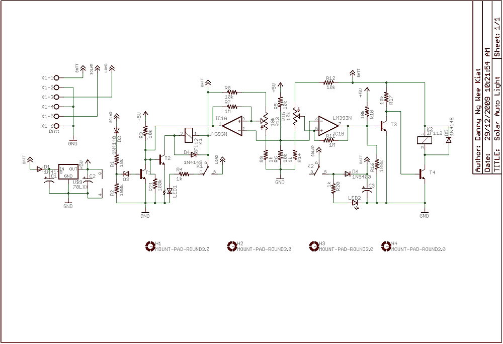
Few years back, I had been working on a project for solar auto lighting. The light will turn on when the solar panel voltage drop below a set point indicating that it is dark. The detection is done by...
Powered by a solar panel, the circuit provides a 5V pure regulated DC voltage. It consists of an oscillator transistor and a regulator transistor. The solar panel charges the battery when sunlight is sufficient to generate a voltage above...