
True RMS Watt Meter

The watt meter circuit described is designed to measure electrical power in a specific range, accommodating home circuit parameters. The core component of the design is a shunt resistor, which is crucial for measuring current. The selection of a 0.001 Ohm shunt resistor allows for accurate measurement of current flowing through the circuit, which can be calculated using Ohm's law. This low resistance value minimizes the impact on the circuit being measured while still providing sufficient voltage drop for measurement.
The design features a shunt configured in an inverted V shape, which is beneficial for spatial efficiency and thermal management. The five loops of wire increase the effective surface area, allowing for better heat dissipation during operation, which is particularly important at higher power levels. The choice of #16 AWG wire is suitable for handling the current without excessive heating, but it is essential to verify the wire gauge against the expected load to ensure safety and reliability.
The output of the shunt is typically connected to an analog or digital voltmeter, which interprets the voltage drop across the shunt and converts it into a power reading. This conversion involves multiplying the measured voltage by the current flowing through the circuit, which can be calculated based on the known resistance of the shunt. The design allows for a maximum measurement of 1500 Watts, aligning with the common household circuit breaker ratings.
To enhance the accuracy of the watt meter, it is recommended to calibrate the device against known power sources. This ensures that the readings reflect true power consumption, accounting for any potential discrepancies in component tolerances or environmental factors. Overall, this circuit provides a practical solution for monitoring power usage in residential applications, offering insights into energy consumption and facilitating better energy management.This circuit will give you a good, Accurate Watt Meter that can measure various power levels. In the Origional Article the Shunt was a .001 Ohm Copper Shunt giving a 1000 Watt Scale. However, because Most Circuit Breakers in homes are 15 Amps, I made my unit to have a range of Zero to 1500 Watts. The Shunt on my unit is comprised of 5 small LOOPS in a Single piece of wire in an Inverted V Shape or an " _n_n_n_n_n_ " Shape, going from pad to pad. I used a #16 AWG wire, but you need to determine wire size and lengths based on the wattage r 🔗 External reference
Related Circuits
The circuit does not present particular difficulties for somebody that has a small experience. The two circuits are the himself, with a small difference only in their input, when they have they measure voltage or current and in connection...
This project and your efforts will provide you with a 0.55...3 watt input to easily 10 watt output. The two linear amplifiers are meant for use with QRP SSB/CW/FM/AM transmitters on the amateur bands 15 and 17 meters can...
Below is a thermostat circuit I recently built to control a 1300 watt space heater. The heater element (not shown) is connected in series with two back to back 16 amp SCRs (not shown) which are controlled with a...
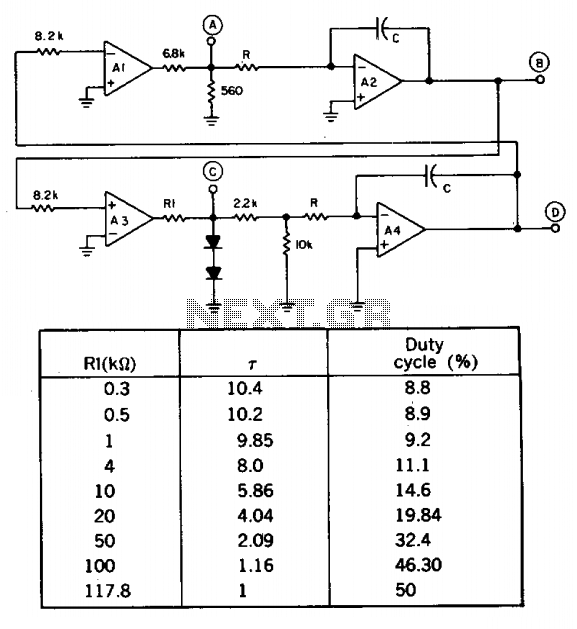
A quad op amp can simultaneously generate four synchronized waveforms. The two comparators (A1 and A3) produce square and pulse waves, while the two integrators (A2 and A4) generate triangular and sawtooth waves. Resistor R1 sets the duty cycle...
The following circuit illustrates a 14 Watt Compact Fluorescent Electronic Ballast Circuit Diagram. Features: it is similar to a 16 Watt circuit, 14 Watt. The 14 Watt Compact Fluorescent Electronic Ballast Circuit is designed to efficiently drive compact fluorescent lamps...
A simple Field Strength Meter consists of a small antenna, a detector diode, a resistor, a capacitor, and a micro ammeter. This circuit is sensitive enough to detect HF fields when positioned close to the transmitting antenna. The circuit...