
Tube for a shunt voltage regulator
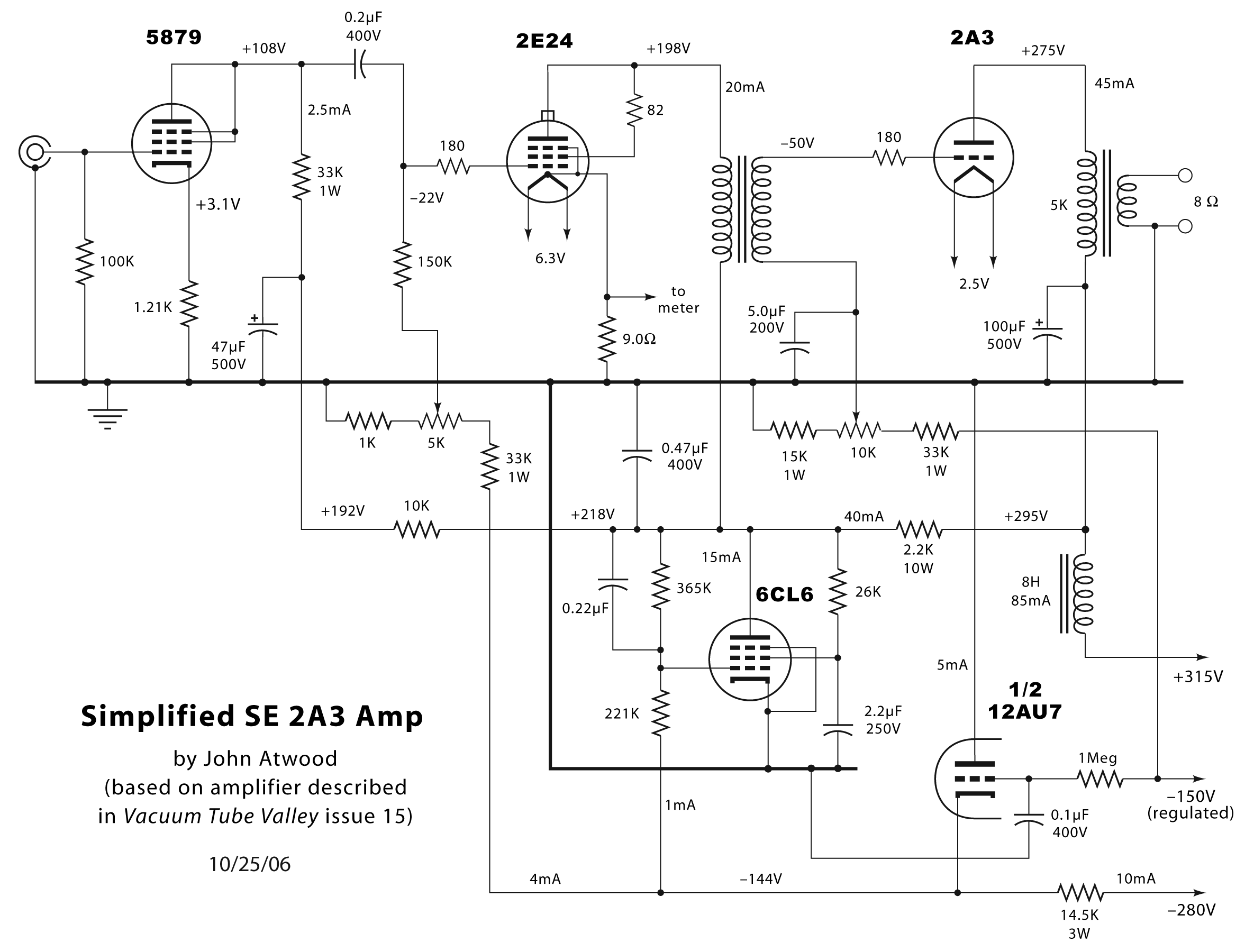
The described circuit configuration includes a Field Effect Transistor (FET), a Zener diode, and a resistor, which can be utilized for voltage regulation or signal conditioning applications. The FET serves as a switch or amplifier, while the Zener diode is used for voltage clamping to maintain a stable output voltage regardless of fluctuations in input voltage or load conditions.
In scenarios where the current flowing through the circuit is within the specified limits of the Zener diode, the FET and resistor components can be omitted. This simplifies the design and reduces component count, enhancing reliability and efficiency.
When a P-channel FET is selected, it can be used in high-side switching applications, allowing for control of the load connected to the positive supply voltage. The gate of the P-channel FET is typically connected to a control signal, which, when pulled low, turns on the FET, allowing current to flow from the source to the drain.
For proper operation, it is essential to reference the datasheets of the selected components to ensure they meet the voltage and current requirements of the application. The Zener diode should be chosen based on its reverse breakdown voltage, which must align with the desired output voltage level. The resistor, if utilized, should be calculated to limit the current through the Zener diode to a safe level, ensuring it operates within its specified power dissipation limits.
This configuration can be effectively employed in power supply circuits, signal processing applications, or as a part of more complex electronic systems where voltage regulation is critical. or take one FET, one Zener, and one resistor. No FET and resistor needed if the current is in the range of specs for a zener. Or take a P-channel.. 🔗 External reference
Related Circuits
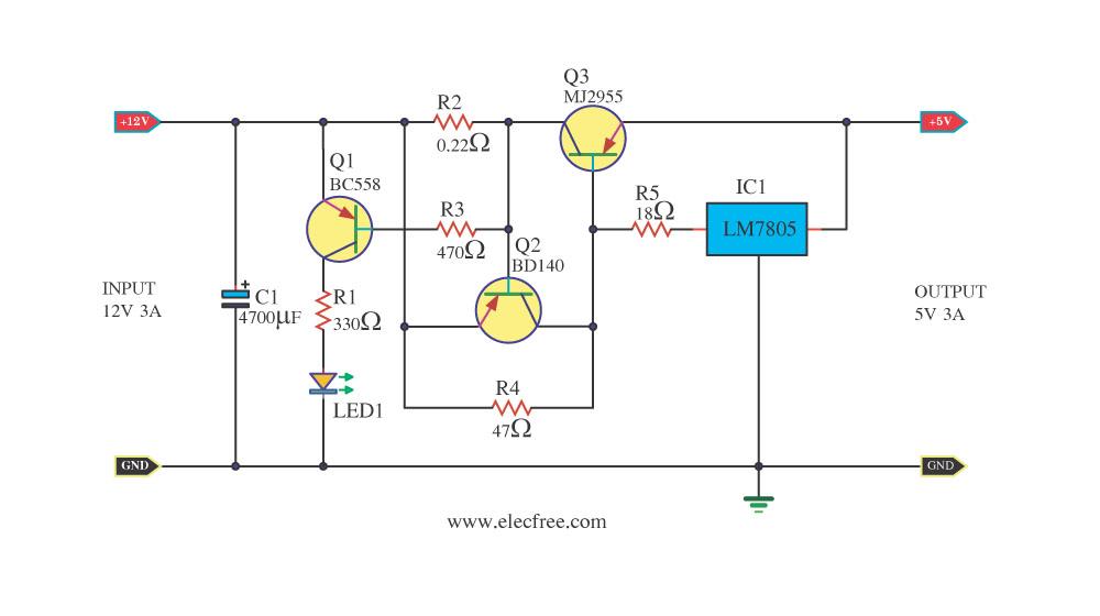
Today, a 12V to 5V 3A DC converter step-down regulator circuit has been presented. Sometimes, individuals have a 12V 3A power supply but require a 5V 3A output for digital circuits. This circuit fulfills that requirement by utilizing standard...
In Fig. 1 A precision DC undervoltage relay switch. The op-amp is wired as a voltage comparator, with a reference voltage applied to pin 2 and the test voltage applied to pin 3: the relay turns on when the...
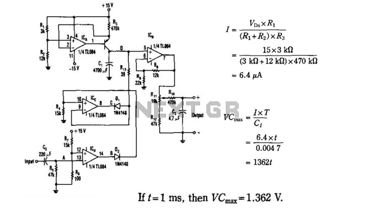
The input signal drives the ICD. Because the positive input (V+) of the ICD is slightly offset to +0.1 V, its steady-state output will be around +13 V. This voltage is sent to the ICC through D2, which sets...
The LM317 is capable of providing extremely good load regulation, but a few precautions are needed to obtain maximum performance. For best performance, the programming resistor (R1) should be connected as close to the regulator as possible to minimize...
There are numerous circuits designed for low voltage regulators. However, for higher voltages, such as those required for valve circuits, the approach differs. This is the reason for the design of a simple regulator capable of handling these voltages....
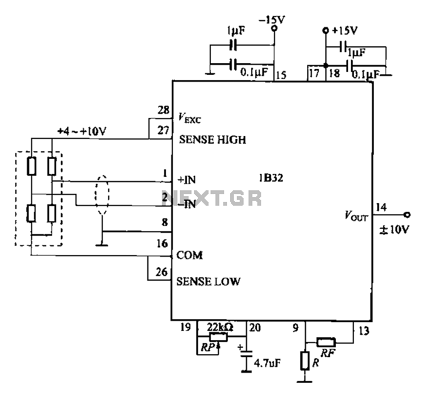
The circuit for bridge measurements is straightforward, as illustrated in the figure. The sensor bridge drive voltage can be adjusted between +4V and +10V, depending on the specific requirements of the sensor. Two fixed gain options of 333.3 and...
Warning: include(partials/cookie-banner.php): Failed to open stream: Permission denied in /var/www/html/nextgr/view-circuit.php on line 713
Warning: include(): Failed opening 'partials/cookie-banner.php' for inclusion (include_path='.:/usr/share/php') in /var/www/html/nextgr/view-circuit.php on line 713