
Tube mic Connecting the capsule 1

In a typical tube microphone circuit, the configuration of the microphone capsule is crucial for optimal performance. The single-sided microphone capsule operates by varying its capacitance due to sound pressure variations. This capacitance change is essential for generating an audio signal, necessitating a polarization voltage to maintain a potential difference across the diaphragm and backplate. The choice of applying this voltage to the diaphragm versus the backplate can significantly influence the circuit design and performance.
In the specified circuit, the backplate is polarized at 60V, achieved through a resistive divider connected to the high-voltage B+ supply. A capacitor is incorporated to filter and stabilize the polarizing voltage, ensuring consistent performance. The diaphragm, which is directly linked to the tube grid, allows for an efficient transfer of the audio signal. The high-value resistor Rg serves to ground both the grid and the membrane, establishing the necessary potential difference that enables the microphone to function effectively.
The sensitivity of the microphone can be fine-tuned by adjusting the polarization voltage, allowing for adaptability in various acoustic environments. The small current generated by the changing capacitance is amplified by the tube, resulting in a clear audio output. Notably, the omission of the grid resistor in certain designs, as highlighted in Royer's article, showcases an alternative approach that can yield effective results while simplifying the circuit.
When the capsule backplate is connected to the microphone body, the design constraints change. Direct polarization of the diaphragm becomes necessary to maintain functionality. However, care must be taken to block the DC voltage from affecting the tube's operating points, which is achieved through the use of a coupling capacitor. The choice of capacitor is critical, as different types may impart varying characteristics to the audio signal, thus a high-quality capacitor is recommended for this application.
Lastly, the inclusion of an additional high-value polarizing resistor is vital to maintain the integrity of the audio signal, preventing attenuation that could arise from the stabilizing capacitor. The Neumann-Gefell CMV563 exemplifies this approach, being compatible with bayonet-style capsules, thereby illustrating the practical application of these concepts in professional audio equipment design.Even in the simplest of tube microphone circuits, there are different approaches to connecting the microphone capsule to the tube. Let`s use a single-sided microphone capsule as our starting point. The capsule behaves as a variable capacitor, changing its capacitance in response to changes in air pressure (i.
e. sound). In order to generate a signal , the capsule needs to be polarised by some voltage, creating a difference in potential between the diaphragm and the back plate. This is the first decision that needs to be made - should the polarising voltage be applied to the diaphragm or the capsule backplate In the circuit shown on the left, the backplate of the microphone is polarised at 60V, which is obtained from the B+ supply, via a resistive divider and a small capacitor to stabilise and filter the polarising voltage.
The membrane is connected directly to the tube grid, and a high value resistor (Rg, typically 100 k ©to 1000 k ©) connects both the grid and the membrane to ground. We have our potential difference across the membrane, and the sensitivity of the mic may be adjusted by increasing and decreasing the polarisation voltage.
As the capacitance of the capsule changes in response to sound, a tiny current will flow through Rg, and this signal is amplified by the tube. In some cases the grid resistor may be omitted. In the circuit below, which appeared in an article in Tape Op magazine by Dave Royer, the capsule diaphragm is grounded by grid leakage rather than a `real` resistor.
It works perfectly. This simple arrangement is not possible when the capsule backplate is mechanically (and electrically) connected to the body of the microphone. In this case the diaphragm must be polarised directly. However, having a voltage of around 60V on the tube grid this would adversely change the operating points of the tube circuit, and so a capacitor must be used to block the DC voltage (left).
Some listeners claim to hear the difference between different types of capacitors, and so normally a very high quality type should be used in this position. An additional high value polarising resistor is also required, otherwise the high impedance audio signal would be attenuated through the stabilisation cap.
An example of this method of connection is the Neumann-Gefell CMV563, which is designed to be used with bayonette style capsules such as the M7, M8 and M9. 🔗 External reference
Related Circuits
In the present day, a wide variety of sensors are available to measure almost anything. This tutorial will explore the fascinating world of sensors, starting with a very simple analog temperature sensor, the LM35. The process of interfacing it...
Recently, a music synthesizer has been constructed using vacuum tubes. Although designed primarily as a percussion synthesizer, it can also be controlled via a keyboard or a MIDI to CV converter. The initial module developed is a dual voltage-controlled...
TB6556FG is a 3-phase full-wave sine-wave PWM brushless motor controller. It features sine-wave PWM control and includes a built-in triangular-wave generator with a carrier cycle defined as fosc/252 (Hz). The device also offers a built-in lead angle control function...
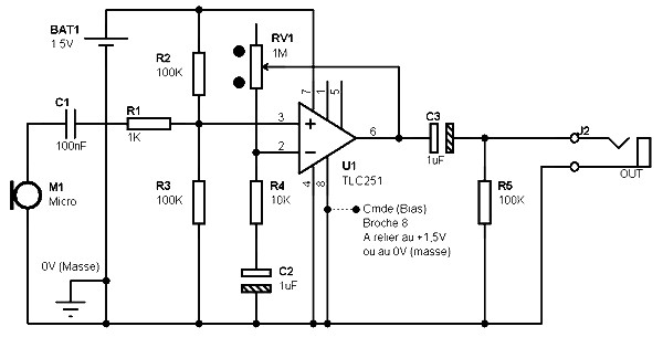
The schematic for a microphone preamplifier utilizes the TLC251, a programmable low-power operational amplifier. A control input, referred to as BIAS (pin 8), determines the operational mode of the amplifier. When this pin is connected to the positive potential...
The interest in tube circuits remains significant. Therefore, I will provide a comprehensive circuit of a preamplifier that is sufficiently detailed. It is primarily composed of the main preamplifier department, the input selector department, application voltage delay, and the connection...

The microcontroller design features the microcontroller (MCU) in hibernation mode, which can only be awakened by a pulse (high-low-high) signal on the reset pin (active low). An accelerometer or an external real-time clock (RTC) serves as the wake-up source....